
Dielectrophoresis micro-fluidic chip for selecting and focusing cells as well as alignment-free microprocessing method thereof

A microfluidic chip and dielectrophoresis technology, applied in the direction of stress-stimulated microbial growth, biochemical equipment and methods, specific-purpose bioreactors/fermenters, etc., can solve the problem of controlling cell trajectory, inability, and increasing complexity and other problems to achieve the effect of improving the separation purity

Active Publication Date: 2019-03-12
BEIJING UNIV OF CHEM TECH
View PDF3 Cites 10 Cited by
  • Summary
  • Abstract
  • Description
  • Claims
  • Application Information

AI Technical Summary

Problems solved by technology

However, most of the dielectrophoretic cell sorting microchips reported so far use planar microelectrodes or three-dimensional microelectrode structures with uniform sidewalls, such as Chinese patent 201510585845.6 and Chinese patent 201510379158.9. Such electrodes cannot generate effective electric field gradients along the channel depth. , unable to control the cell trajectory in the vertical direction
In a series of reports from 2013 to 2015, the Yobas research group of the Hong Kong University of Science and Technology proved that the three-dimensional silicon electrode structure can generate an electric field gradient along the depth of the channel, and layer the cells in the vertical direction to improve the separation purity, but the used The processing technology of silicon-based electrodes is complex and expensive; while the method of using lower-cost conductive polymers to process three-dimensional microelectrodes all adopts the above-mentioned electrode structure with uniform sidewalls, which cannot control the cell trajectory in the vertical direction. In addition, its electrodes and The flow channel needs to be processed separately using different materials, so an additional sacrificial layer photolithography is required to define the flow channel in each processing process. After the electrode filling is completed, the sacrificial layer needs to be removed and the flow channel material is filled again to form the flow channel. Processing The process is time consuming and adds complexity

Method used


Image

  • Dielectrophoresis micro-fluidic chip for selecting and focusing cells as well as alignment-free microprocessing method thereof
  • Dielectrophoresis micro-fluidic chip for selecting and focusing cells as well as alignment-free microprocessing method thereof
  • Dielectrophoresis micro-fluidic chip for selecting and focusing cells as well as alignment-free microprocessing method thereof

Examples


Embodiment 1

[0072] In this example, the dielectrophoretic microfluidic chip obtained in the above embodiment and polystyrene microspheres as cell models were used to test the effect of particle sorting. The specific steps are as follows:

[0073] The polystyrene microsphere solution was diluted with deionized water (DI Water) to obtain a mixed solution of 2 μm microspheres and 15 μm microspheres, wherein the concentrations of 2 μm microspheres and 15 μm microspheres were 1×10 8 / ml and 5×10 6 pieces / ml. The mixed solution was injected into the above-mentioned dielectrophoresis microfluidic chip at a flow rate of 0.15 ml / h. The input amplitude from the main electrodes 7 at both ends is 30V pp , a sinusoidal signal with a frequency of 20kHz, and observe the trajectory of the microsphere under a microscope.

[0074] It has been observed that when no electrical signal is input, 2 μm microspheres and 15 μm microspheres are dispersed in the entire flow channel and move along the outlet 25 in...

Embodiment 2

[0076] In this example, the dielectrophoretic microfluidic chip obtained in the above embodiment and the mixed solution of red blood cells and polystyrene microspheres were used to test the effect of particle sorting. The specific steps are as follows:

[0077] Use 300mM D-mannitol solution to dilute human blood, mix the diluted blood with a solution of 7 μm microspheres whose size is similar to that of blood cells, and obtain a mixed solution of two kinds of particles, the solution conductivity is 0.01S / m, and The concentration of both blood cells and 7 μm microspheres was 1 × 10 7 pieces / ml. The mixed solution was also injected into the above-mentioned dielectrophoresis microfluidic chip at a flow rate of 0.15 ml / h. The input amplitude from the main electrode 7 at both ends is 35V pp , a sinusoidal signal with a frequency of 1MHz, observe the trajectory of the two particles under a microscope.

[0078] It has been observed that when no electrical signal is input, blood ce...

Embodiment 3

[0080] In this example, the dielectrophoretic microfluidic chip obtained in the above embodiment and diluted human blood are used to test the effect of cell focusing. The specific steps are as follows:

[0081] Use 300mM D-mannitol solution to dilute human blood to obtain a blood cell concentration of 4×10 7 A / ml solution, the solution conductivity is 0.02S / m. The mixed solution was also injected into the above-mentioned dielectrophoresis microfluidic chip at a flow rate of 0.15 ml / h. The input amplitude from the main electrode 7 at both ends is 35V pp , a sinusoidal signal with a frequency of 100kHz, observe the movement track of blood cells under a microscope.

[0082] It has been observed that when no electrical signal is input, the blood cells are dispersed in the entire flow channel and move toward the outlet 25 along with the flow direction of the solution, such as Figure 11 (a) shown. After the electrical signal is input, the blood cells are repelled by the negativ...


PUM

PropertyMeasurementUnit
Conductivityaaaaaaaaaa

Abstract

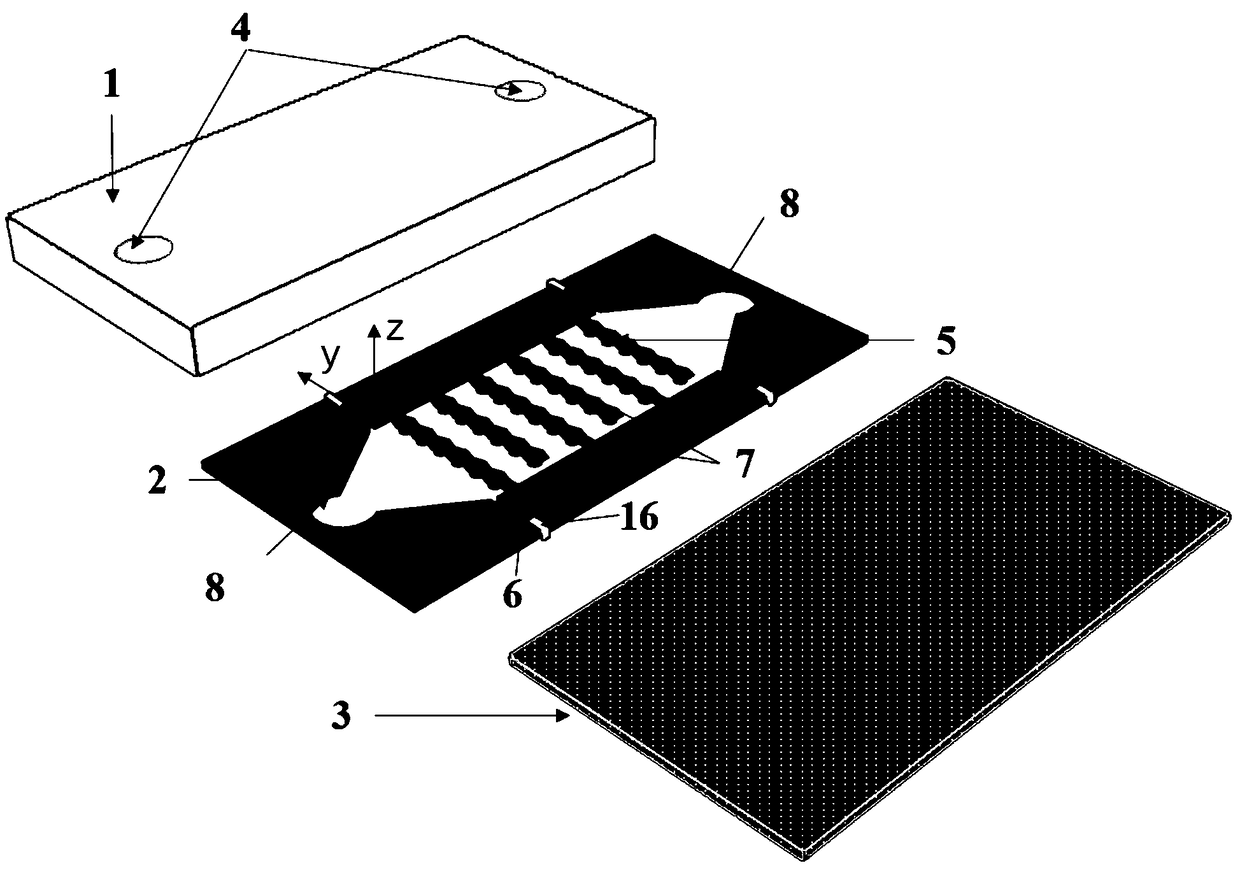
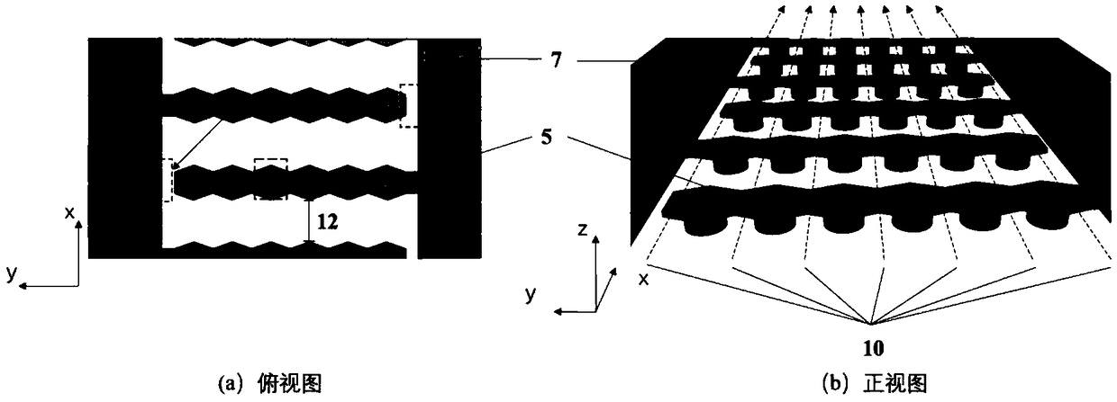
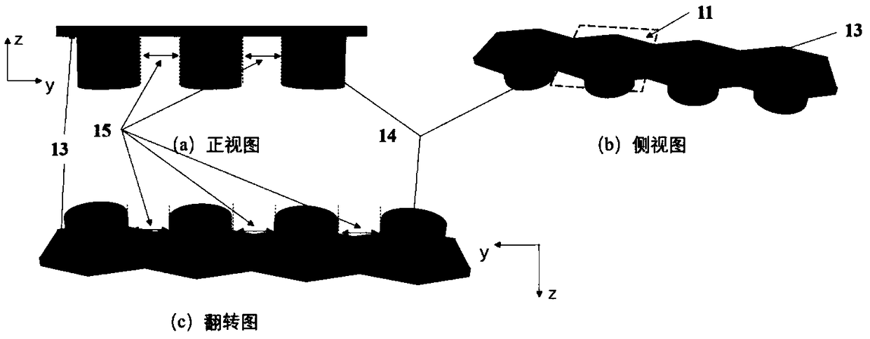
The invention relates to a dielectrophoresis micro-fluidic chip for selecting and focusing cells as well as an alignment-free microprocessing method thereof, which belongs to the technical field of micro-fluidic chip. The dielectrophoresis micro-fluidic chip comprises a substrate layer, an integrated runner-electrode functional layer and a top layer, whereinthe integrated runner-electrode functional layer comprises a main body electrode, an interdigital electrode extending into a main runner from a main electrode and perpendicularly crossing the main runner, a main runner inlet, a main runneroutlet, parallel branch runners formed by dividing the main runner by virtue of non-uniform side wall structures of the interdigital electrode and an insulation channel. High-performance dielectrophoresis forces in the horizontal direction and vertical direction are generated by virtue of the interdigital electrode formed by multiple layers of electrodes and having the non-uniform side walls so asto improve the separation purity, the cell focusing can be realizedat the same time, and the flux can be improved by virtue of the parallel runners formed by the non-uniform side walls; and an SU-8 mold with a multilayer structure is filled in one step by using a homogenous conductive polymer, and the integrated runner-electrode structure can be formed in one step by reversing the mold.

Description

technical field [0001] The invention belongs to the technical field of cell sorting and control in microfluidic chip technology, and in particular relates to a dielectrophoretic microfluidic chip for cell sorting and focusing and an alignment-free processing method thereof. Background technique [0002] Cell sorting technology refers to the technology of separating a cell from a multicellular sample. Cell sorting is a biological experimental method often used in diagnostic testing, pathological research and other disciplines, and it is of great significance for the early diagnosis and prognosis of many diseases. In the method of cell sorting, the traditional centrifugation technology requires a large sample volume and low separation purity; while flow cytometry, which can achieve precise separation, is expensive and requires professional personnel to operate, and more importantly, it requires the cells. Additional fluorescent staining or labeling can affect the physiologica...

Claims


Application Information

Patent Timeline
IPC IPC(8): C12M1/00C12M1/42
CPCC12M23/16C12M35/02
Inventor 邢晓星聂小凤张忠乐
Owner BEIJING UNIV OF CHEM TECH
Learn More