
Manufacturing method of high heat conduction iron base plate

A production method and technology of iron substrate, applied in the field of circuit board manufacturing, can solve problems such as insufficient surface hardness, high cost, easy oxidation and rust, etc., achieve strength and toughness and processing characteristics, good product formability, and improve thermal conductivity Effect

Active Publication Date: 2019-03-15
ZHEJIANG LEUCHTEK ELECTRONICS
View PDF5 Cites 0 Cited by
  • Summary
  • Abstract
  • Description
  • Claims
  • Application Information

AI Technical Summary

Problems solved by technology

Compared with other metal substrates, the hardness of the iron substrate is much greater in terms of manufacturing process and difficulty, and it is difficult for ordinary manufacturers to master the technology
The main technical difficulties are: 1) Iron materials are easily oxidized and rusted during processing, which will lead to poor bonding with the insulating and heat-conducting layer and abnormal delamination; 2) Insufficient surface hardness, which is extremely difficult during production and customer use It is easy to scratch, which is a bottleneck for the quality cost of the product, as well as the processability and applicability of the product; 3) the cost is high, in order to solve the binding force, processability and applicability, it needs to invest in high equipment and scrap costs
Therefore, the scope of application in the market is limited by the cost. In addition, there is also the problem that the thermal conductivity of the substrate is not good, and it cannot effectively meet the high heat dissipation requirements of electromechanical equipment.

Method used


Image

  • Manufacturing method of high heat conduction iron base plate
  • Manufacturing method of high heat conduction iron base plate
  • Manufacturing method of high heat conduction iron base plate

Examples


Embodiment 1

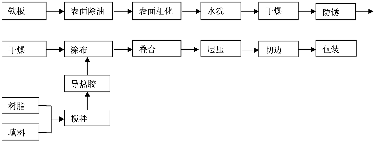
[0040] A method for manufacturing a high thermal conductivity iron substrate, the steps comprising:

[0041] S1. Production of iron substrate: 1) Put the iron plate with a thickness of 1.50mm into the lye with a concentration of 10% and a temperature of 55°C to degrease for 3 minutes; One-sided grinding and coarsening; 3) Wash the iron plate with high-pressure water; 4) Anti-rust treatment of the iron plate with 10% anti-rust agent; 5) Anti-rust treatment with hot air at 130°C The final iron plate is dried to obtain an iron base plate.

[0042] S2. Preparation of heat-conducting glue: fully mix epoxy resin and modified nano-inorganic filler according to the mass ratio of 15:80, stir at 1500r / min for 4 hours to obtain a mixed adhesive solution, and then use a nano-scale ceramic grinder to mix The adhesive solution was ground twice, and finally the adhesive solution after grinding was stirred at a rotational speed of 1500r / min for 5 hours, and then put into a magnet for magneti...

Embodiment 2

[0051] A method for manufacturing a high thermal conductivity iron substrate, the steps comprising:

[0052] S1. Production of iron substrate: 1) Put the iron plate with a thickness of 1.0mm into the lye with a concentration of 20% and a temperature of 50°C to remove oil for 3 minutes; 2) Use a 600-mesh grinding wheel on the iron plate after degreasing Carry out single-sided brushing and coarsening; 3) wash the iron plate with high-pressure water; 4) carry out anti-rust treatment on the iron plate with 13% water-based anti-rust agent configured; 5) use 140°C hot air to The iron plate after antirust treatment is dried to obtain the iron base plate.

[0053] S2. Preparation of heat-conducting glue: fully mix epoxy resin and modified nano-inorganic filler according to the mass ratio of 10:70, stir at 1200r / min for 4 hours to obtain a mixed adhesive solution, and then use a nano-scale ceramic grinder to mix The adhesive solution was ground twice, and finally the adhesive solution...

Embodiment 3

[0062] A method for manufacturing a high thermal conductivity iron substrate, the steps comprising:

[0063] S1. Production of iron substrate: 1) Put the iron plate with a thickness of 1.0mm into the alkali solution with a concentration of 10% and a temperature of 50°C for 2 minutes; 2) Use a 400-mesh grinding wheel on the iron plate after degreasing Carry out single-sided brushing and coarsening; 3) wash the iron plate with high-pressure water; 4) carry out anti-rust treatment on the iron plate with 10% water-based anti-rust agent configured; 5) use 120 ℃ hot air to The iron plate after antirust treatment is dried to obtain the iron base plate.

[0064] S2. Preparation of heat-conducting glue: fully mix epoxy resin and modified nano-inorganic filler according to the mass ratio of 15:75, stir at 2200r / min for 6 hours to obtain a mixed adhesive solution, and then use a nano-scale ceramic grinder to mix The adhesive solution was ground twice, and finally the adhesive solution a...


PUM

PropertyMeasurementUnit
particle sizeaaaaaaaaaa
thicknessaaaaaaaaaa
electric potential / voltageaaaaaaaaaa

Abstract

The invention provides a manufacturing method of a high heat conduction iron base plate. The manufacturing method mainly comprises six following steps: firstly, manufacturing an iron base plate; secondly, using epoxy resin and a modified nanometer inorganic heat conduction filler to prepare heat conduction glue water; thirdly, roller-coating a release film with the heat conduction glue water, drying and cooling to obtain a heat conduction glue film; fourthly, carrying out plate combined overlapping on a copper foil, the heat conduction glue film and the iron base plate according to certain sequence; fifthly, carrying out heating compression molding formation on a plate combination in a vacuum environment; and sixthly, carrying out trimming on a heat conduction iron base plate meeting the requirement and putting in storage. According to the heat conduction iron base plate prepared in the invention, the nanometer inorganic filler is modified, and good interference bonding is formed between the modified nanometer inorganic filler and epoxy resin, so that the two-phase interface heat resistance is reduced, and the heat conductivity and the tenacity of the material are improved.

Description

technical field [0001] The invention belongs to the technical field of circuit board manufacturing, and in particular relates to a method for manufacturing a high thermal conductivity iron substrate. Background technique [0002] The iron substrate is a metal heat dissipation substrate used in high-end motors, high-end product equipment and motors, and is currently widely used in the market. Compared with other metal substrates, the hardness of iron substrates is much greater in terms of manufacturing process and difficulty, and it is difficult for ordinary manufacturers to master the technology. The main technical difficulties are: 1) Iron materials are easily oxidized and rusted during processing, which will lead to poor bonding with the insulating and heat-conducting layer and abnormal delamination; 2) Insufficient surface hardness, which is extremely difficult during production and customer use It is easy to scratch, which is a bottleneck for the quality cost of the pro...

Claims


Application Information

Patent Timeline
Patent Type & Authority Applications(China)
IPC IPC(8): B32B37/12B32B37/10B32B37/06B32B37/08B32B38/00H05K3/02
CPCB32B37/06B32B37/08B32B37/1018B32B37/12B32B38/0004B32B2307/302B32B2307/558B32B2457/08H05K3/022
Inventor 楼红卫
Owner ZHEJIANG LEUCHTEK ELECTRONICS
Learn More