Eureka AIR delivers breakthrough ideas for toughest innovation challenges, trusted by R&D personnel around the world.

Sludge treatment system and method

A sludge treatment and sludge technology, applied in the field of self-heating sludge treatment system, can solve the problems of excessive flue gas and dust in fluidized fluidized furnace, difficulty in drying municipal sludge, and high drying cost, so as to reduce the degradation of sludge organic matter, reduce Sewage discharge volume, effect of improving flammability

Pending Publication Date: 2019-03-29
湖南碧汇泉环保科技有限公司 +1
View PDF0 Cites 0 Cited by
  • Summary
  • Abstract
  • Description
  • Claims
  • Application Information

AI Technical Summary

Problems solved by technology

Using sludge as fuel, especially papermaking sludge and municipal sludge, which itself contains a large amount of organic matter, can be directly used as fuel after drying. However, the current sludge drying equipment generally requires high-temperature flue gas as a fuel for sludge drying. Heat source, high-temperature flue gas mostly comes from hot blast stoves, traditional hot blast stoves cannot burn sludge with low calorific value, especially for municipal domestic sewage treatment plants, because there is no heat source, municipal sludge is difficult to dry, such as burning with coal to produce high-temperature smoke If gas is used as a heat source, the drying cost is too high and it is not economically cost-effective. However, using sludge as fuel has the following problems: (1) Although municipal domestic sludge contains high organic matter, the effective calorific value of sludge after drying can reach 2000kcal / kg, but the sludge with this calorific value is difficult to use in the ordinary chain furnace boiler; (2) When the effective calorific value of the sludge reaches 2000kcal / kg, the fluidized fluidized furnace can be used in theory, but the dry sludge produced by the existing drying equipment Most of the mud is powdery or lumpy. This kind of powdery or lumpy sludge is difficult to use in fluidized furnaces and needs to be granulated before use; (3) Using fluidized furnace flue gas directly as a heat source has high thermal efficiency, but fluidized fluidized furnace flue gas dusty

Method used


Image

  • Sludge treatment system and method
  • Sludge treatment system and method
  • Sludge treatment system and method

Examples


Embodiment Construction

[0031] The present invention will be described in detail below in conjunction with examples. It should be noted that, in the case of no conflict, the embodiments of the present invention and the features in the embodiments can be combined with each other. For the convenience of description, if the words "up", "down", "left" and "right" appear in the following, it only means that the directions of up, down, left and right are consistent with the drawings themselves, and do not limit the structure.

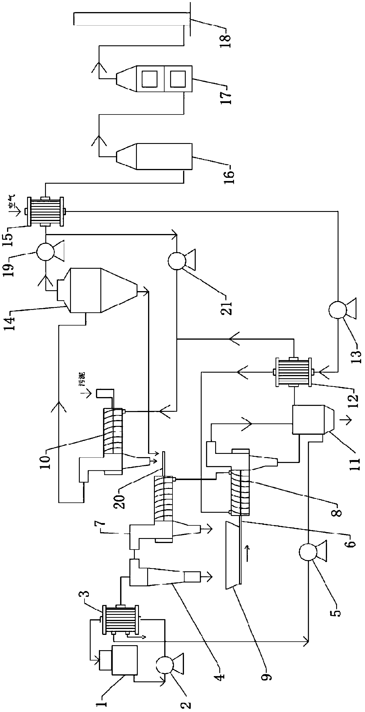
[0032] Such as figure 1 As shown, a sludge treatment system includes a first drum dryer 10, a second drum dryer 7, a third drum dryer 8, a fluidized fluidized furnace 11, a first heat exchanger 12, and a second heat exchanger 15. The third drum dryer is a jacketed drum dryer;

[0033] The discharge port of the first drum dryer 10 communicates with the feed port of the second drum dryer 7, the discharge port of the second drum dryer communicates with the feed port of the third drum...


PUM


Abstract

The invention relates to a sludge treatment system and method. The sludge treatment system comprises a first roller dryer, a second roller dryer, a third roller dryer, a boiling furnace, a first heatexchanger and a second heat exchanger, and the third roller dryer is a jacketed-type roller dryer; a discharging outlet of the first roller dryer communicates with a feeding inlet of the second rollerdryer, a discharging outlet of the second roller dryer communicates with a feeding inlet of the third roller dryer, and a discharging outlet of the third roller dryer communicates with the boiling furnace. According to the sludge treatment system and method, self-heat of sludge basically serves as a heat source, energy consumption is less, waste is treated by waste, the volume of generated fly ash is small, the sludge can be used as building materials, and thus the sludge can be subjected to resource utilization to the utmost extent; and in addition, the sludge treatment system and method arenot limited by the production scale and have large popularization value.

Description

technical field [0001] The invention relates to a sludge treatment system and method, in particular to a self-heating sludge treatment system and method. Background technique [0002] Sludge is the product of sewage treatment, which is an extremely complex heterogeneous body composed of organic debris, bacterial cells, inorganic particles, colloids, etc. The main characteristics of sludge are high water content (up to 99%), high content of organic matter, easy to rot and smell, and the particles are finer, the specific gravity is smaller, and it is in a colloidal liquid state. Sludge contains a large amount of organic matter, such as benzene, chlorophenols, polychlorinated biphenyls (PCBs), polychlorinated dibenzofurans (PCDFs) and polychlorinated dibenzodioxins (PCDDs), etc.; parasite eggs, etc. Pathogenic microorganisms; heavy metals such as cadmium, chromium, copper, nickel, mercury, lead and zinc, if not handled properly, can easily cause secondary pollution to the envi...

Claims


Application Information

Patent Timeline
IPC IPC(8): C02F11/13F23G7/00
CPCF23G7/001C02F11/12
Inventor 晏永祥
Owner 湖南碧汇泉环保科技有限公司
Why Eureka
Eureka Blog
Learn More