Stable organic luminescent radical polymer and OLED device based on same

A technology of electroluminescent devices and free radicals, which can be applied in the fields of electro-solid devices, semiconductor devices, semiconductor/solid-state device manufacturing, etc., and can solve problems such as restricting applications.

Active Publication Date: 2019-03-29
JILIN UNIV
View PDF4 Cites 6 Cited by
  • Summary
  • Abstract
  • Description
  • Claims
  • Application Information

AI Technical Summary

Problems solved by technology

However, there are many uncontrollable factors in this doping method, such as aggregation quenching caused by phase separation, etc.
In addition, the aggre

Method used


Image

  • Stable organic luminescent radical polymer and OLED device based on same
  • Stable organic luminescent radical polymer and OLED device based on same
  • Stable organic luminescent radical polymer and OLED device based on same

Examples


Embodiment 1

[0027] Example 1: Synthesis of Polymer 1

[0028] first step:

[0029]

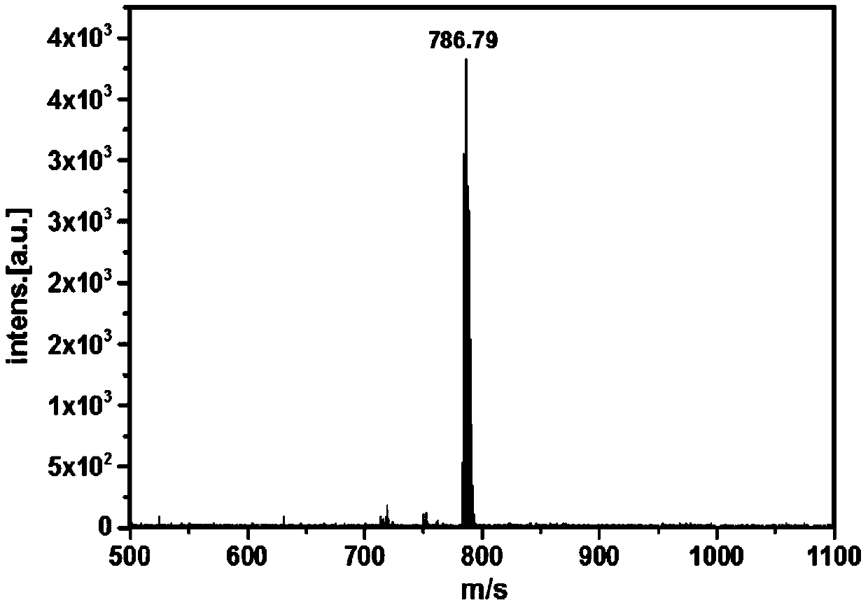
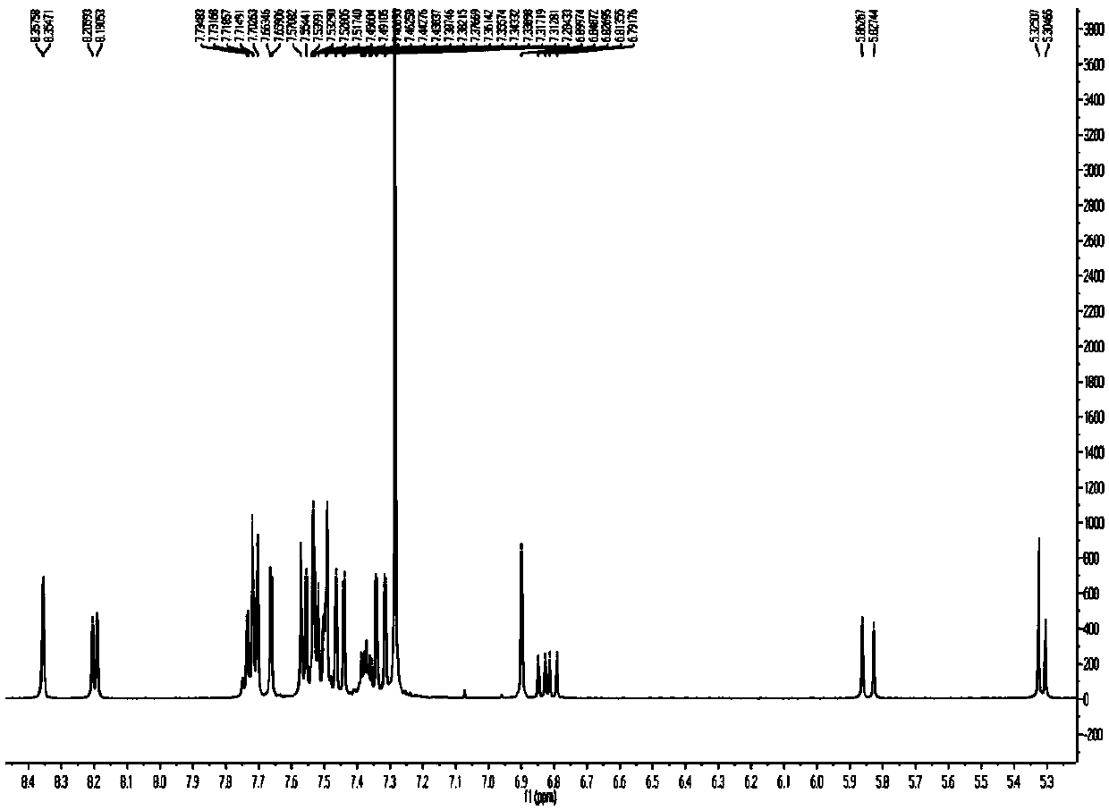
[0030] Add 10.14g (55.9mmol) 1,3,5-trichlorobenzene, 0.5mL (6.2mmol) chloroform, 0.91g (6.8mmol) anhydrous aluminum trichloride to a thick-walled pressure bottle, and heat to 80°C for 2.5 After cooling to room temperature for h, the reaction mixture was poured into 1M hydrochloric acid solution, extracted three times with chloroform, dried over anhydrous sodium sulfate, and the solvent was distilled off, and purified by column chromatography with petroleum ether as an eluent to obtain 2.8 g of white solid A1. 1 H-NMR (500MHz, CDCl 3 ): δ7.39(d, J=2.4Hz, 3H), 7.26(d, J=2.2Hz 3H).6.71(s, 1H); MS(m / z): 553.65[M] + .

[0031] Step two:

[0032]

[0033] Under argon protection, add 150mL of anhydrous THF, 6g (10.80mmol) and 1.8g (16.2mmol) of potassium tert-butoxide to a 250mL two-necked bottle for 5 hours, then add 7.17g (29.16mmol) of chloranil for 1.5 hours After the reaction, the solvent was dis...

Embodiment 2

[0049] Example 2: Synthesis of Polymer 2

[0050] first step

[0051]

[0052] The synthesis procedure is the same as that of compound A6, except that the styrene in the reaction is replaced with acrylonitrile, and compound B1 is finally obtained.

[0053] second step

[0054]

[0055] The synthesis procedure is the same as that of polymer 1, except that A6 in the reaction is replaced by B1, and finally free radical polymer 2 is obtained.

Embodiment 3

[0056] Example 3: Synthesis of Polymer 3

[0057] first step

[0058]

[0059] Under argon protection, 6ml of toluene, N-vinylcarbazole (0.1eq), A5 (1eq) and AIBN (0.2eq) were added to a 50mL polymer bottle, and the temperature was raised to 70°C for 24h. After the reaction was completed, it was cooled to room temperature, and the reaction solution was slowly added dropwise into 50 mL of ice methanol under stirring, continued to stir for 24 h, filtered, and dried. The crude product was subjected to a methanol Soxhlet extractor for 36 hours, and finally 0.50 g of white polymer C1 was obtained. GPC:M w =2.3×10 4 , M w =2.5×10 4 ,PDI=1.1.

[0060] second step

[0061]

[0062] The synthesis procedure is the same as that of polymer 1, except that A6 in the reaction is replaced by C1, and finally free radical polymer 3 is obtained.


PUM


Abstract

A stable organic luminescent radical polymer material and an organic light-emitting device produced from the same belong to the technical field of organic luminescence. The radical polymer material which can emit lights in a solid form is successfully obtained by a design strategy of suspending a luminescent radical monomer on a polymer main chain, the polymer main chain can be selected from polyethylene and other non-conjugated main chains and polycarbazole and other conjugated main chains, and the suspended luminescent free radical can be selected from a tris(2,4,6-trichlorophenyl)methyl radical, a perchlorobenzyl radical and a bis(2,4,6-trichlorophenyl)methyl radical and derivatives thereof. The free radical polymer material has good magnetic properties, the polymer skeleton improves the solubility and the photostability of the radical material, and the spectral wavelength of the light-emitting device produced through a spin coating process of the material is 684 nm.

Description

technical field [0001] The invention belongs to the technical field of organic electroluminescence, and in particular relates to a stable organic light-emitting radical polymer material applied to electroluminescence and an organic electroluminescent device (OLED) prepared by using the polymer material. Background technique [0002] In 2015, Li Feng et al. invented an organic electroluminescent device using stable organic light-emitting radicals as the light-emitting layer (US Patent No. 9,935,271B2; Angew.Chem., Int.Ed., 2015, 54, 7091-7095.). This type of OLED device using organic light-emitting radicals uses doublet excitons to emit light, completely avoiding the problem of triplet excitons in traditional OLEDs, and the maximum internal quantum efficiency of the device can reach 100% (ACS Appl.Mater.Interfaces, 2016, 8, 35472-35478; Nature, 2018, 563, 536-540;). Stable luminescent radicals have high luminescence efficiency in solution, but do not emit light in the solid ...

Claims


Application Information

Patent Timeline
IPC IPC(8): C08G61/12C08F212/14C08F212/08C08F220/44C08F226/12H01L51/50H01L51/54
CPCC08F212/14C08G61/124C08G2261/95C08G2261/5222C08G2261/411C08G2261/122C08G2261/146C08G2261/143C08G2261/3241H10K85/111H10K50/11C08F212/08C08F220/44C08F226/12
Inventor 李峰阿力木·阿卜杜热合曼张明
Owner JILIN UNIV
Why Eureka
Try Eureka