Sensitive microrna optical fiber sensing device and its production and measurement method

A technology of optical fiber sensing and fabrication method, applied in the field of biomedical optical sensing technology design, can solve problems such as insufficient sensitivity, achieve low detection limit, high sensitivity, and enhance the effect of evanescent field energy

Active Publication Date: 2021-07-27
JINAN UNIVERSITY
View PDF0 Cites 0 Cited by
  • Summary
  • Abstract
  • Description
  • Claims
  • Application Information

AI Technical Summary

Problems solved by technology

[0004] Optical fiber biosensors have the potential to meet the above requirements. It is small, flexible, low-cost, and resistant to electromagnetic interference, but its sensitivity is far from meeting the requirements of single-molecule detection.

Method used


Image

  • Sensitive microrna optical fiber sensing device and its production and measurement method
  • Sensitive microrna optical fiber sensing device and its production and measurement method
  • Sensitive microrna optical fiber sensing device and its production and measurement method

Examples


Embodiment 1

[0049] Optical fiber sensing technology uses light waves as the information carrier, and has the advantages of low cost, compact structure, high sensitivity, remote monitoring, corrosion resistance, and strong biocompatibility. It has become one of the most rapidly developing biosensing technologies in recent years. In the relevant reports of fiber optic biosensing research, high performance fiber optic interferometer has become a research hotspot. The most representative one is the tapered micro-nano optical fiber interferometer sensor developed in recent years. In addition to the characteristics of conventional optical fiber sensors, this type of optical fiber sensor can also use the evanescent wave mode excited by it that is sensitive to the surrounding environment , not only greatly enriched its detection objects, but also improved the measurement accuracy. Moreover, the manufacturing cost is low, meets the use requirements of disposable clinical medical devices, and has v...

Embodiment 2

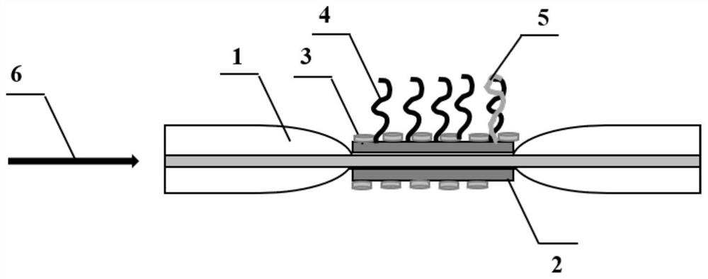
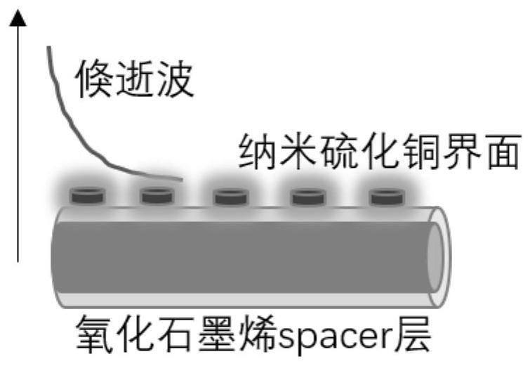
[0055] Such as figure 1 As shown, this embodiment provides a method for detecting small molecule microRNA with enhanced sensitivity to optical fiber sensors, the method comprising: drawing a photosensitive optical fiber on a flame into a tapered micro-nano optical fiber interferometer 1 with a diameter of 6.5 microns , the tapered micro-nano fiber interferometer 1 is fused with a single-mode fiber to make a fiber sensor; the graphene oxide spacer layer 2 is assembled into a single-layer film on the side of the tapered micro-nano fiber interferometer 1, and the plasmon resonance Nano-copper sulfide particles with peaks in the 1500-1600nm region are assembled on the spacer layer to form an interface layer; the single-stranded DNA probe 4 is fixed on the surface of the interface layer through covalent bonding; after the single-stranded DNA probe 4 is fixed, the The optical fiber sensor is immersed in the solution containing microRNA, and the light source 6 is input into the taper...


PUM

PropertyMeasurementUnit
diameteraaaaaaaaaa
diameteraaaaaaaaaa
diameteraaaaaaaaaa

Abstract

The invention discloses a sensitivity-enhancing micro-RNA optical fiber sensing device and a method for making and measuring the device. The device includes a tapered micro-nano optical fiber, a graphene oxide spacer layer, nano-copper sulfide and a DNA probe; the tapered micro-nano optical fiber The transition region and the uniform region form an interference structure, which is used as an optical fiber sensing probe and is fused with a single-mode optical fiber; the graphene oxide spacer layer is assembled into a single-layer film on the side of the micro-nano region of the optical fiber; nano-copper sulfide is assembled on the graphene oxide through electrostatic attraction surface; the DNA probe is fixed on the surface of the optical fiber through covalent bonds; The evanescent wave on the side of the nanofiber is sensitive to changes in the external environment, and the change in the refractive index caused by the specific combination of microRNA and DNA probes is detected. The invention realizes the identification and measurement of single-molecule microRNA.

Description

technical field [0001] The invention relates to an optical fiber sensing device, in particular to a sensitive microRNA optical fiber sensing device and a manufacturing and measuring method, belonging to the field of biomedical optical sensing technology design. Background technique [0002] MicroRNA, as a class of endogenous non-protein-coding RNA molecules, exists in plants, humans and animal tissues, consists of 18-25 nucleotides, and is a group of short, non-coding RNAs widely present in eukaryotes The single-stranded RNA family of proteins. The expression of microRNA is tissue-specific and stage-specific, that is, different types of microRNA are expressed in different tissues, and different microRNA expressions are expressed in different stages of biological development. Since most human diseases are related to the disordered expression of microRNA, it has been used as a diagnostic biomarker in recent years, and its detection is of great significance in cancer diagnosis...

Claims


Application Information

Patent Timeline
Patent Type & Authority Patents(China)
IPC IPC(8): G01N21/45G01N21/01
CPCG01N21/01G01N21/45G01N2021/458
Inventor 黄赟赟陈鹏伟关柏鸥
Owner JINAN UNIVERSITY
Why Eureka
Try Eureka