A kind of synthesis method and application of ionic liquid loaded porous material
A technology for ionic liquids and porous materials, which is applied in the field of synthesis of ionic liquid-loaded porous materials, and can solve problems such as cumbersome preparation methods and uneven loading of ionic liquids
- Summary
- Abstract
- Description
- Claims
- Application Information
AI Technical Summary
Problems solved by technology
Method used
Image

Examples
Embodiment 1
[0071] Heating the semi-solidified ionic liquid at a certain temperature can obtain a fluid liquid. In order to further explore the temperature of this state change, ionic liquids with different anion and cation ratios are heated with 1°C as the heating temperature unit, and Observe the change of its state, the temperature of the state change is T f Expressed, see Table 1. The results show that when Et 3 NHCl and CuCl 2 When the molar ratio is 1:1, T f =50°C, with Et 3 NHCl and CuCl 2 With the increase (>1:1) or decrease (f increase. In will Et 3 NHCl and anhydrous CuCl 2 According to a certain molar ratio, the heating temperature can be referred to as T f . Therefore, Et 3 NHCl·CuCl 2 Ionic liquids as modifiers.
[0072] Table 1 Et 3 NHCl and CuCl 2Heating temperature for the synthesis of ionic liquids with different molar ratios
[0073]
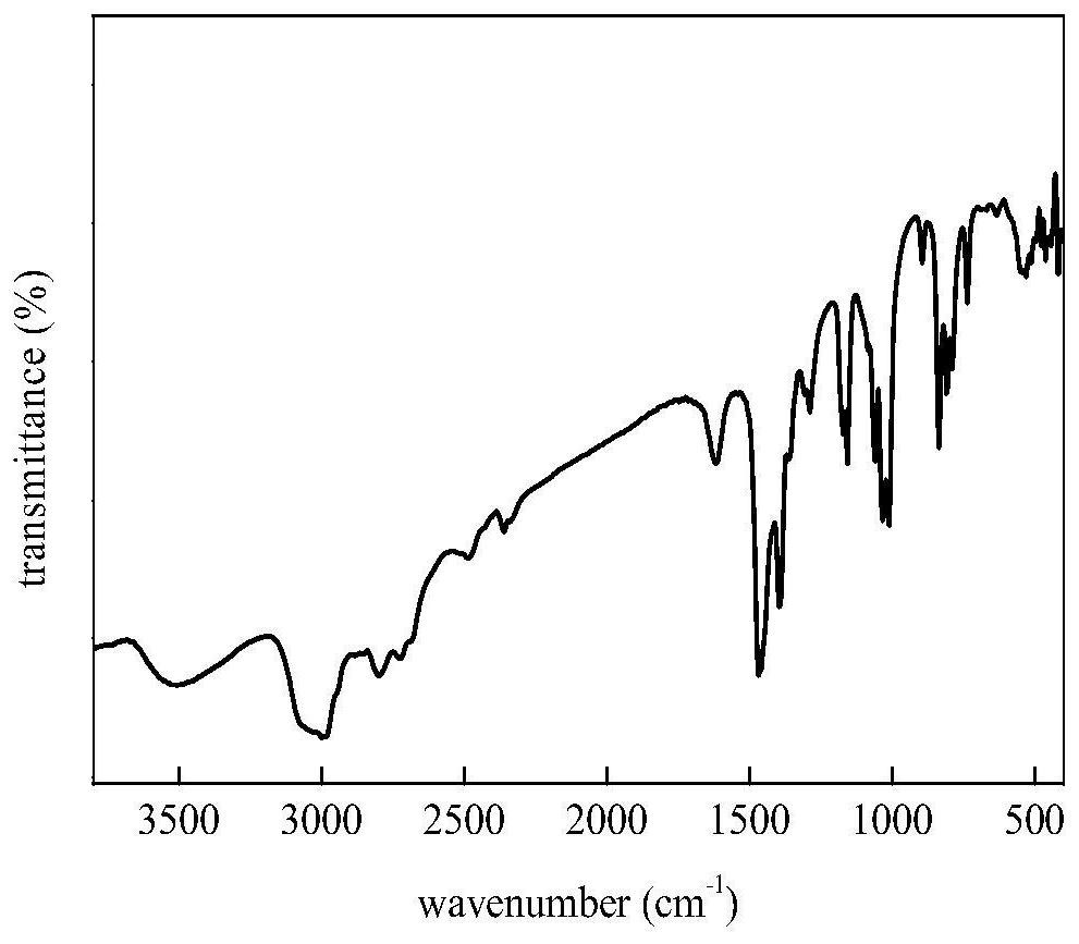
[0074] To the Et that embodiment 1 obtains 3 NHCl·CuCl 2 Ionic liquids were characterized by infrared spectroscopy, s...
Embodiment 2
[0076] Using ethanol as a dispersant, add 10g of silica gel to 200mL of absolute ethanol and stir at 50°C, add 0.506g-2.024g of Et 3 After stirring with NHCl for 1h, add 0.494g-1.976g of anhydrous CuCl 2 After stirring for 6 h, the ethanol was evaporated to dryness to obtain an in-situ bifunctional ionic liquid-modified silica gel, which was denoted as IL-SG (in-situ). The activated carbon, resin, and activated alumina adsorbents obtained by the same modification method were denoted as IL-AC (in-situ), IL-AAO (in-situ) and IL-ABS (in-situ), respectively. See Table 2 for the amount of ionic liquid-loaded porous material raw materials.
[0077] The ex-situ loading method of the bifunctional ionic liquid loaded porous material corresponding to the in situ loading method of the bifunctional ionic liquid loaded porous material, the steps are as follows:
[0078] Add 10g of silica gel into 200ml of absolute ethanol and stir, and add 1-4g of Et 3 NHCl·CuCl 2 , stirred at 50° C. f...
Embodiment 3
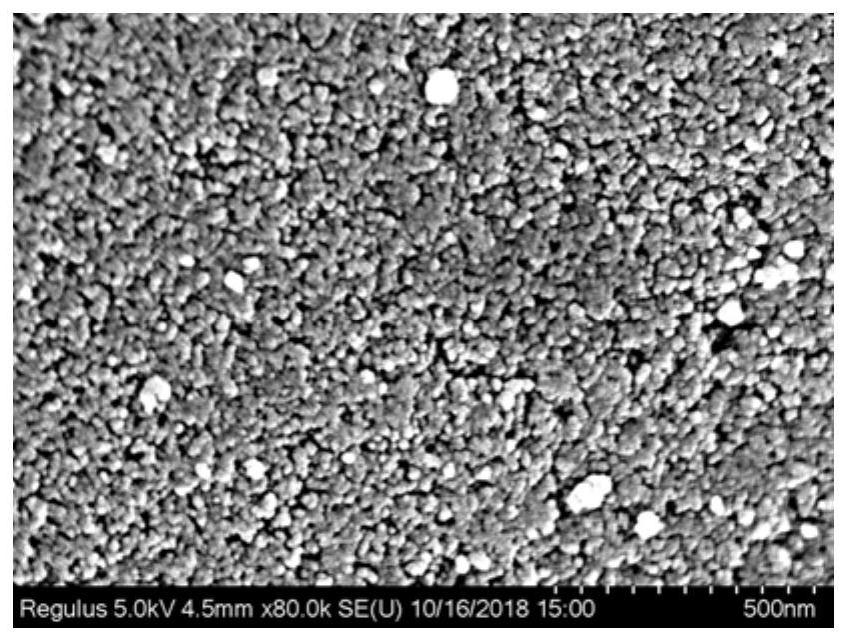
[0084] No. 1, No. 12 and No. 8 adsorbents obtained in embodiment 2 are characterized by SEM, see respectively image 3 , Figure 4 and Figure 5 . in, image 3 The No. 1 adsorbent is in-situ bifunctional ionic liquid-loaded silica gel IL-SG (in-situ), with a loading capacity of 10wt%. It can be seen that it still has a rich pore structure, which is similar to that of Figure 4 The No. 12 adsorbent is very similar to silica gel without loading ionic liquid, while Figure 5 The No. 8 adsorbent is the SEM image of non-situ bifunctional ionic liquid loaded silica gel IL-SG (non-in-situ), the loading capacity is 10wt%, it can be seen that its surface presents large aggregates, and some pores It was blocked by ionic liquids, indicating that the in-situ loading method can achieve more uniform dispersion of ionic liquids and maintain the porous structure of the material than the traditional loading method.
PUM
 Abstract
Description
Claims
Application Information
 - R&D
- Intellectual Property
- Life Sciences
- Materials
- Tech Scout
- Unparalleled Data Quality
- Higher Quality Content
- 60% Fewer Hallucinations
Browse by: Latest US Patents, China's latest patents, Technical Efficacy Thesaurus, Application Domain, Technology Topic, Popular Technical Reports.
© 2025 PatSnap. All rights reserved.Legal|Privacy policy|Modern Slavery Act Transparency Statement|Sitemap|About US| Contact US: help@patsnap.com