Method for preparing optical fiber mirror by ultrasonic fusion coating on optical fiber end face

An optical fiber end face, ultrasonic technology, applied in cladding optical fiber, optical waveguide light guide, coating, etc., can solve the problems of reflective mirror displacement, large curing stress, coating layer cracks, etc., and achieve simple coating process and high coating quality , low cost effect

Active Publication Date: 2021-02-19
BEIJING INFORMATION SCI & TECH UNIV
View PDF6 Cites 0 Cited by
  • Summary
  • Abstract
  • Description
  • Claims
  • Application Information

AI Technical Summary

Problems solved by technology

This structure has the hidden danger of glue filling in the optical path or air gap in the optical path, as well as the displacement of the reflector, which affects the optical performance index and reliability of the device.
[0003] In addition, before the reflective lens is pasted, when the optical fiber is bonded and fixed with a ceramic ferrule, epoxy resin glue is usually used. Cracks in the coating layer occur at the bonding interface of the coating layer, which reduces the bending resistance of the fiber optic mirror pigtail, and will lead to device failure in severe cases

Method used


Image

  • Method for preparing optical fiber mirror by ultrasonic fusion coating on optical fiber end face
  • Method for preparing optical fiber mirror by ultrasonic fusion coating on optical fiber end face
  • Method for preparing optical fiber mirror by ultrasonic fusion coating on optical fiber end face

Examples


Embodiment Construction

[0016] The technical solutions in the embodiments of the present invention will be clearly and completely described below in conjunction with the accompanying drawings.

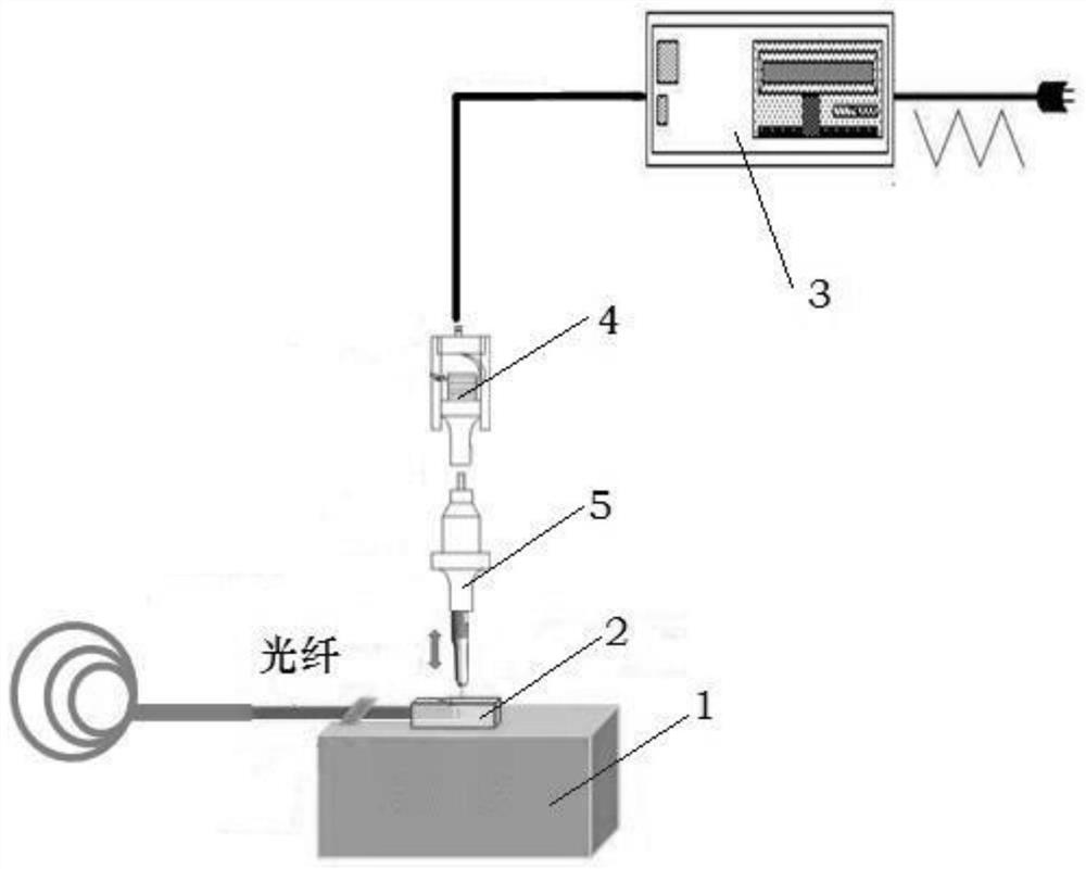
[0017] Such as figure 1 As shown, a kind of fusion coating system for optical fiber reflector includes a heating platform 1 and an ultrasonic system. The heating platform 1 is provided with a Teflon rectangular groove 2. The ultrasonic system includes a high-frequency power supply 3 connected to a pressure-based The transducer 4 of the electric ceramic crystal, the output end of the transducer 4 is connected with a temperature-adjustable ultrasonic welding head 5 .

[0018] A method for preparing an optical fiber mirror by ultrasonic fusion coating on the end face of an optical fiber, comprising the following steps:

[0019] Take the single-mode optical fiber, remove the acrylate coating on the surface, wipe it with a dust-free paper dipped in alcohol, and cut it with an optical fiber cutter to obtain a flat...


PUM

PropertyMeasurementUnit
reflectanceaaaaaaaaaa

Abstract

The invention discloses a method for preparing an optical fiber reflector by melting and coating the end surface of an optical fiber with ultrasonic waves. The method comprises the following steps that an acrylate coating layer on the surface of a single-mode optical fiber is removed, wiping with dust-free paper dipped with alcohol is carried out, and cutting with an optical fiber cutting knife iscarried out to obtain a flat optical fiber end surface; one end of the cut optical fiber is put into a teflon rectangular groove placed on a heating platform, and the temperature of the heating platform is set at 300 DEG C; a special tin alloy with a melting point of 290 DEG C is molten in the teflon rectangular groove; an ultrasonic generator is turned on, the ultrasonic frequency is set at 64 KHz and the temperature of an ultrasonic welding head is set at 400 DEG C, ultrasonic waves are injected into the molten tin alloy, and the end face of the optical fiber is coated for 10 min; and the temperature of the heating platform is lowered to 20 DEG C for cooling, and after the coated optical fiber is cooled down, and the optical fiber is separated from the teflon rectangular groove and putinto a constant temperature box with the temperature set at 80 DEG C for 24 h annealing treatment to obtain the optical fiber reflector.

Description

technical field [0001] The invention relates to the technical field of optical fiber sensing, in particular to a method for preparing an optical fiber reflector by using ultrasonic fusion coating on the end face of an optical fiber. Background technique [0002] Optical fiber mirror is one of the basic passive devices in the field of optical fiber communication and optical fiber sensing, and its function is to realize the reflection of light in the optical path. At present, the optical fiber reflectors used in the field of optical fiber communication and optical fiber sensing use reflective mirrors pasted on the end faces of optical fibers to achieve internal reflection of light in the optical path. This structure has hidden dangers of glue filling in the optical path or an air gap in the optical path, as well as displacement of the reflective lens, thereby affecting the optical performance index and reliability of the device. [0003] In addition, before the reflective len...

Claims


Application Information

Patent Timeline
Patent Type & Authority Patents(China)
IPC IPC(8): C23C2/08C23C2/38G02B5/08G02B6/02
CPCC23C2/08C23C2/38G02B5/0808G02B6/02052
Inventor 祝连庆张钰民戎丹丹董明利娄小平刘锋宋言明
Owner BEIJING INFORMATION SCI & TECH UNIV
Why Eureka
Try Eureka