Catalytic cracking process and catalytic cracking system

A catalytic cracking and process technology, which is applied in the field of catalytic cracking process and system, can solve the problem of no further conversion of light hydrocarbons, and achieve the effects of promoting cracking again, increasing the conversion rate of heavy oil, and improving catalyst activity

Active Publication Date: 2019-04-23
CHINA PETROLEUM & CHEM CORP +1
View PDF15 Cites 1 Cited by
  • Summary
  • Abstract
  • Description
  • Claims
  • Application Information

AI Technical Summary

Problems solved by technology

But the light hydrocarbons are not further converted, so the yield of light olefins will not be very high

Method used


Image

  • Catalytic cracking process and catalytic cracking system
  • Catalytic cracking process and catalytic cracking system

Examples


Embodiment approach

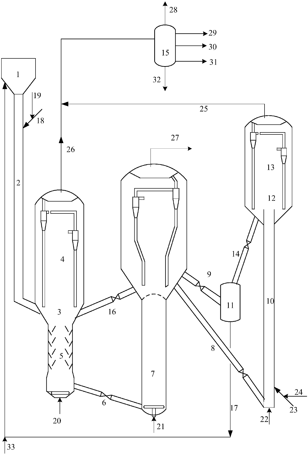
[0064] According to the present invention, the second product and the second spent catalyst leaving the first fluidized bed reactor enter the settling section, and after settling to separate the second spent catalyst carried therein, the second product is introduced into a subsequent product separation device. In the product separation device, the second product is separated to obtain dry gas, liquefied gas, gasoline, diesel oil and oil slurry. The second fluidized bed reactor and the first fluidized bed reactor may share a set of product separation device. At this time, the two streams of products are mixed and then introduced into the product separation device. For example figure 1 As shown, the system can also include a product separation device 15, the inlet of the product separation device 15 can be communicated with the product outlet of the first fluidized bed reactor 3 and the product outlet of the second fluidized bed reactor 12 , the product separation device 15 may...

Embodiment 1

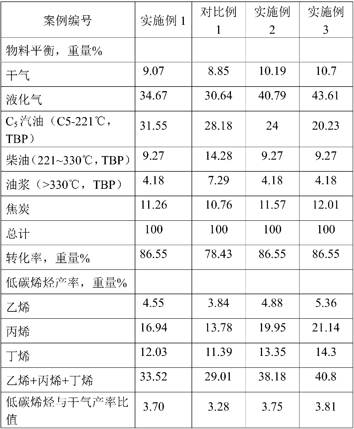
[0070] The test was carried out in a medium-sized catalytic cracking unit. The device includes a set of independent reaction regeneration system: the reactor is a downcomer reactor plus a fluidized bed combination reactor, the inner diameter of the riser is 16 mm, and the length is 3200 mm, and the fluidized bed reaction at the bottom outlet of the downcomer reactor The diameter (inner diameter) of the fluidized bed reactor is 64 mm and the height is 600 mm. The catalyst used is MMC-2 catalyst, which cracks the raw materials shown in Table 1; the oil and gas after the reaction are separated from the catalyst, and the catalyst enters the stripper for stripping and then enters the regenerator for regeneration, and the regenerated catalyst leaves the regenerator in two ways , all the way into the fluidized bed reactor, increase the reaction temperature and the ratio of agent to oil in the fluidized bed reactor. The other way enters the catalyst mixing tank, and then enters the c...

Embodiment 2

[0074] Referring to Example 1, the difference is that the regenerated catalyst leaves the regenerator in three ways, one way enters the fluidized bed reactor, the other way enters the catalyst mixing tank, and then enters the catalyst tank at the top of the downcomer reactor, and the third way enters the lifting tube reactor. Riser reactor internal diameter is 12 millimeters, and length is 2200 millimeters, and the catalyzer that adopts is MMC-2 catalyzer, to the light gasoline (distillation range is 30-85 ℃ that is 30-85 ℃, olefin content is 52 weight percents) rich in olefins from product separation unit , the weight of light gasoline accounts for 15% by weight of the weight of heavy raw materials) for cracking, and the resulting oil gas and catalyst mixture is subjected to gas-solid separation in a gas-solid separation device. The separated catalyst enters the catalyst mixing tank to be mixed with the high-temperature regenerant, and then sent to the catalyst tank at the to...


PUM

PropertyMeasurementUnit
Diameteraaaaaaaaaa
Heightaaaaaaaaaa
The inside diameter ofaaaaaaaaaa

Abstract

The present invention relates to a catalytic cracking process and a catalytic cracking system. The catalytic cracking process comprises: a, feeding a heavy raw material into the upper portion of a downer reactor, making the heavy raw material contact a first catalytic cracking catalyst from the top portion of the downer reactor, and carrying out a first catalytic cracking reaction from top to bottom to obtain a first product and a first spent catalyst; and b, feeding the first product and the first spent agent obtained in the step a into a first fluidized bed reactor, making the first productand the first spent agent contact a second catalytic cracking catalyst, carrying out a second catalytic cracking reaction to obtain a second product and a second spent catalyst, feeding the second spent catalyst into a regenerator, and regenerating to obtain a regenerated catalyst. With the process and the system of the present invention, the yield of low-carbon olefins can be increased while theincrease of the dry gas yield can be retarded.

Description

technical field [0001] The invention relates to a process and system for catalytic cracking. Background technique [0002] Small molecule olefins such as ethylene, propylene and butene are the most basic raw materials for organic synthesis. At present, the main production process of small molecular olefins in the world is steam cracking process, but the high temperature cracking furnace is easy to coke, so this process basically uses light oil as raw material, such as natural gas, naphtha, light diesel oil, and hydrogenation can also be used Cracking tail oil is used as raw material. At present, the trend of heavy and inferior crude oil in my country is becoming more and more obvious, the yield of light oil such as naphtha is getting lower, and the contradiction between supply and demand of raw materials for steam cracking process and catalytic reforming process is becoming more and more serious. Since the mid-1980s, Sinopec Research Institute of Petroleum and Chemical Ind...

Claims


Application Information

Patent Timeline
IPC IPC(8): C10G51/02C10G55/06C10G11/18
CPCC10G11/182C10G51/026C10G55/06C10G2300/4006C10G2300/4012C10G2300/4018C10G2300/4025C10G2300/70C10G2300/708C10G2400/02C10G2400/04C10G2400/16C10G2400/20C10G2400/26
Inventor 沙有鑫朱根权谢朝钢杨超成晓洁
Owner CHINA PETROLEUM & CHEM CORP
Why Eureka
Try Eureka