PWM heating control system and method

A heating control and heating control circuit technology, applied in control/regulation systems, ohmic resistance heating, electric heating devices, etc., can solve problems such as power consumption, waste, errors, etc., and achieve strong anti-interference ability, simple structure, and accurate temperature control Effect

Active Publication Date: 2019-04-26
WENHUA UNIV
View PDF5 Cites 4 Cited by
  • Summary
  • Abstract
  • Description
  • Claims
  • Application Information

AI Technical Summary

Problems solved by technology

However, most of its power is consumed in the adjustment resistor, resulting in a great waste
[0004] Manual control method, according to personal sensory judgment, adjust the output

Method used


Image

  • PWM heating control system and method
  • PWM heating control system and method
  • PWM heating control system and method

Examples


Example Embodiment

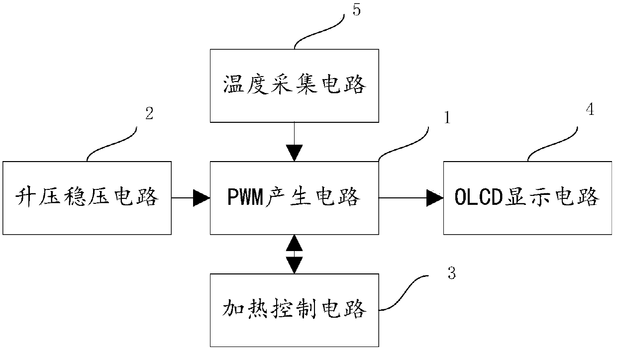
[0029] The present invention will be described in further detail below with reference to the accompanying drawings. The present invention provides a PWM heating control system, such as figure 1 As shown, the system is composed of a PWM generation circuit 1, a boost voltage regulator circuit 2, a heating control circuit 3, an OLED display circuit 4, and a temperature acquisition circuit 5;

[0030] The power output terminal of the boost voltage regulator circuit 2 is connected to the power input terminal of the PWM generating circuit 1, and the first digital input and output terminal of the PWM generating circuit 1 is connected to the digital input and output terminal of the temperature collecting circuit 5, The PWM wave generating terminal of the PWM generating circuit 1 is connected to the signal receiving terminal of the heating control circuit 3, and the second digital input and output terminal of the PWM generating circuit 1 is connected to the input and output terminal of the ...


PUM


Abstract

The invention provides a PWM heating control system and method. According to the system, data information is collected through a temperature sensor, the result is sent to a master controller controlled by a single-chip microcomputer, the master controller generates PWM waves with a corresponding duty ratio by means of processing of the PID algorithm of the single-chip microcomputer, and data is displayed through a display circuit. The state of an NMSO is controlled, then an SX1308 boost control chip is controlled, the aim of controlling heating is achieved, and the temperature is stabilized atthe set temperature.

Description

technical field [0001] The invention relates to the technical field of heating control, in particular to a PWM heating control system and method. Background technique [0002] At present, the mainstream heating control methods are as follows, power control heating, the input and output signals are controlled by the thermostat, and the heating power of the heater is adjusted by the thyristor to control the heating capacity of the heating system. When the temperature value of the heating system is far lower than the set value, the thyristor will output full power. When the temperature of the heating system is close to the set value, the power output of the thyristor will become smaller and smaller. Once the temperature reaches the set value, the power output of the thyristor is zero. Its advantage is that the temperature control effect is good, and it is suitable for some occasions with high temperature requirements, but due to the high cost of its application, the structure...

Claims


Application Information

Patent Timeline
IPC IPC(8): H05B1/02H05B3/00H02M3/158
CPCH02M3/158H05B1/02H05B3/00
Inventor 张新建李克桃易丽华李林董俐瑶
Owner WENHUA UNIV
Why Eureka
Try Eureka