Vacuum pipeline for transmission cavity of semiconductor dry etching machine and control method thereof

A technology of dry etching and evacuating tubes, used in semiconductor/solid-state device manufacturing, circuits, discharge tubes, etc., can solve problems such as leakage, surface defects of wafer products, and contamination of wafer products by annular particles

Active Publication Date: 2019-05-07
SHANGHAI HUALI INTEGRATED CIRCUTE MFG CO LTD
View PDF3 Cites 1 Cited by
  • Summary
  • Abstract
  • Description
  • Claims
  • Application Information

AI Technical Summary

Problems solved by technology

[0006] (3) After the pressure of the back helium pipeline is zero, the electrostatic adsorption plate reverses the voltage to release static electricity (the pressure measurement accuracy of the back helium pipeline is insufficient, Torr (Torr) level)
[0012] (4) The gas leaks into the cavity from the back of the wafer (wafer) edge that has lost the electrostatic adsorption, polluting the cavity environment;
[0014] (6) Contaminated chambers lead to wafer surface defects, forming ring-shaped particles that contaminate wafer products
[0015] It can be seen that since the Lam transmission chamber uses a dry pump to remove residual helium in the electrostatic removal design, the pressure of the transmission chamber is usually set at tens of millitorr (mT). The pressure in the vacuum line is usually around 200 millitorr (mT), such a pressure difference will cause the gas in the end of the vacuum line to pass through the open valve and flow upstream into the vacuum chamber
There are many reaction products left at the end of the vacuum pipeline, and the tiny reaction products enter the process chamber together with the airflow, which will cause surface defects on wafer products

Method used


Image

  • Vacuum pipeline for transmission cavity of semiconductor dry etching machine and control method thereof
  • Vacuum pipeline for transmission cavity of semiconductor dry etching machine and control method thereof
  • Vacuum pipeline for transmission cavity of semiconductor dry etching machine and control method thereof

Examples


Embodiment 1

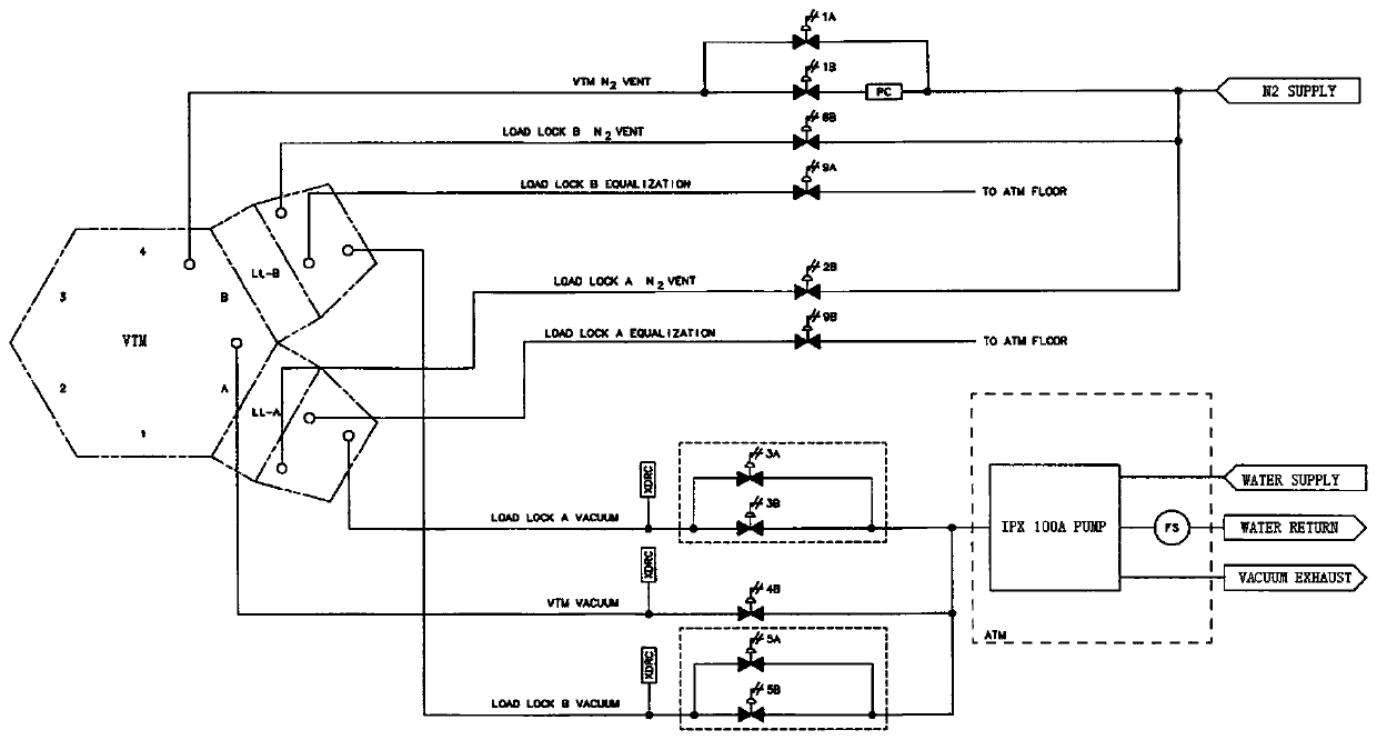
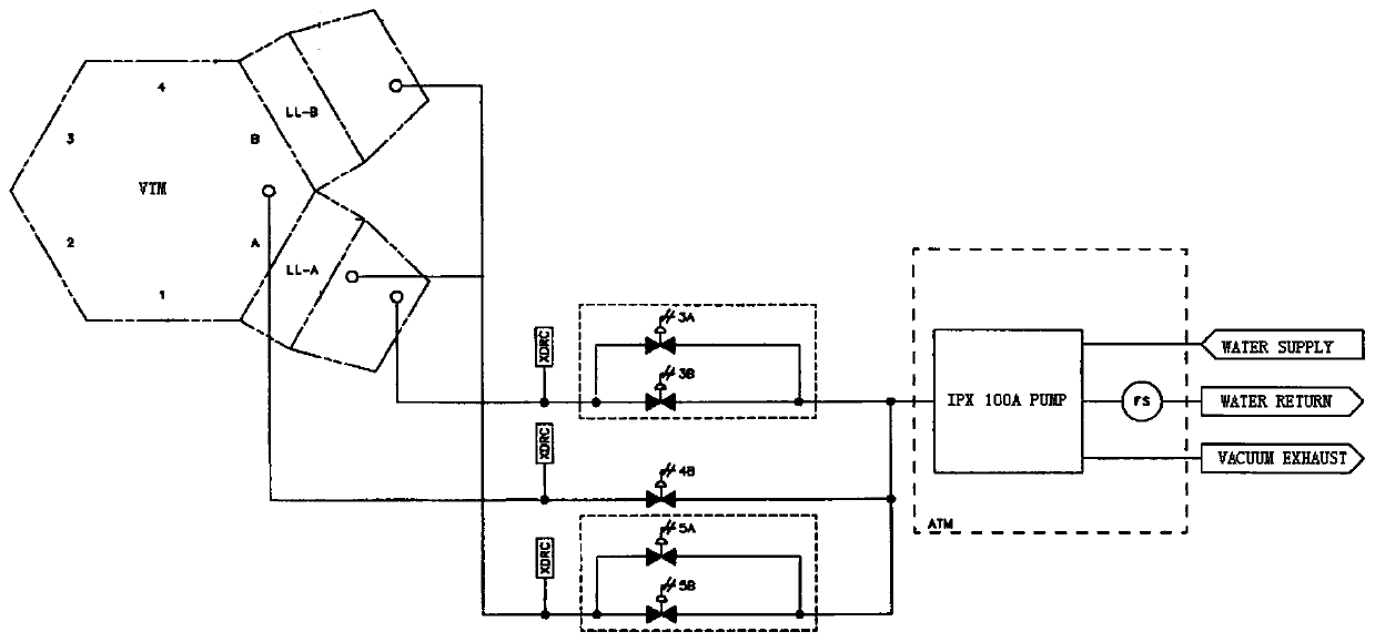
[0042] Vacuum pipeline for the transfer cavity of semiconductor dry etching machine, such as Figure 6 As shown, the vacuum transfer module (VTM) of the semiconductor dry etching machine is connected to the air inlet of the dry pump 1 through a pipeline;

[0043] The buffer chamber 2 is connected to the pipeline between the intake end of the dry pump 1 and the rear end of the helium isolation valve V1;

[0044] The helium front valve V2 is connected to the pipeline between the buffer chamber 2 and the rear end of the helium isolation valve V1;

[0045] The helium post-stage valve V4 is connected to the pipeline between the buffer chamber 2 and the intake end of the dry pump 1;

[0046] The helium pressure gauge 3 is connected to the pipeline between the helium inlet port and the rear end of the helium isolation valve V1;

[0047] The helium supply valve V3 is connected to the pipeline between the helium pressure gauge 3 and the helium inlet port;

[0048] The front end of t...

Embodiment 2

[0053] Based on the evacuation pipeline of the transport chamber of the semiconductor dry etching machine in Embodiment 1, a filter 4 is also provided on the pipeline between the helium supply valve V3 and the helium pressure gauge 3 .

[0054] Preferably, a working valve V5 is provided on the pipeline from the vacuum transfer module (VTM) to the intake end of the dry pump.

[0055] Preferably, the semiconductor dry etching machine is Lam 2300VersysTM Metal / Silicon System.

[0056] Preferably, the dry pump 1 is an iPX 100 type.

[0057] Preferably, the dry pump 1 is installed at the position of the atmospheric transfer module (ATM).

Embodiment 3

[0059] Based on the control method of the silicon etching system transmission chamber vacuum pumping pipeline in the first embodiment, the dry pump 1 uses the vacuum transfer module and the airlock (used as a transfer between the vacuum transfer module (VTM) and the atmospheric transfer module (ATM) Station) vacuuming, usually the vacuum transfer module (VTM) works together with the dry pump through N2purge (N2 purge) to maintain the transmission working pressure at a pressure of 85 mTorr to 95 mTorr (eg 90 mTorr);

[0060] When the transmission is waiting, the helium post-stage valve V4 remains open, and a dry pump is used to evacuate the buffer chamber 2 to 85 mTorr to 95 mTorr (for example, 90 mTorr);

[0061] When removing static electricity, the helium supply valve V3 and the helium back-stage valve V4 are closed, and the helium isolation valve V1 and the helium front-stage valve V2 are opened. The gas in the back helium pipeline is discharged into the buffer chamber, and...


PUM


Abstract

The invention discloses a vacuum pipeline for a transmission cavity of a semiconductor dry etching machine. The vacuum transmission module of the semiconductor dry etching machine is connected to theair inlet end of a dry pump through a pipeline. A buffer chamber is connected to a pipeline between the air inlet end of the dry pump and the rear end of a helium isolation valve. A helium front stagevalve is connected to a pipeline between the buffer chamber and the rear end of the helium isolation valve. A helium rear stage valve is connected to a pipeline between the buffer chamber and the airinlet end of the dry pump. A helium pressure gauge is connected to a pipeline between a helium inlet end and the rear end of the helium isolation valve. A helium supply valve is connected to a pipeline between the helium pressure gauge and the helium inlet end. The front end of the helium isolation valve is connected to an electrostatic adsorption disk through a pipeline. The invention also discloses a control method of the vacuum pipeline for the transmission cavity of the semiconductor dry etching machine. The vacuum pipeline can prevent a process reaction product from contacting the surface of a wafer product through a helium passage, reduces the defects of the wafer, improves the process stability, prolongs a cavity maintenance period, and increases the workshop productivity.

Description

technical field [0001] The invention relates to semiconductor processing equipment, in particular to a vacuum pumping pipeline for a transmission chamber of a semiconductor dry etching machine and a control method thereof. Background technique [0002] The Lam 2300Versys series is the main machine for polysilicon and metal etching launched by LAM. It is an important process machine for wafer processing. As the feature size of wafer processing moves from um to nm technology nodes, plasma etching The control requirements for defects are becoming more and more stringent. Lam 2300VersysTM Metal / Silicon System cavity such as figure 1 As shown, the transfer lumen tubing is as figure 2 As shown, the general diagram of the vacuum system of the transfer chamber pipeline is shown in image 3 As shown, the vacuum system diagram is shown in Figure 4 As shown, the back helium line is as Figure 5 shown. In the design of the platform structure of the Lam 2300VersysTM Metal / Silicon...

Claims


Application Information

Patent Timeline
Patent Type & Authority Applications(China)
IPC IPC(8): H01L21/67H01J37/32H01L21/683
Inventor 袁鹏华沈超李佳俊
Owner SHANGHAI HUALI INTEGRATED CIRCUTE MFG CO LTD
Why Eureka
Try Eureka