Method for recycling C-2 in dry gas of refinery

A refinery dry gas and dry gas technology, applied in chemical instruments and methods, hydrocarbons, absorption purification/separation, etc., can solve the problem of difficult separation of carbon 2 and carbon 3 components, large circulation of carbon 4 absorbent, Large investment and other issues, to achieve the effect of easy acquisition, high recovery rate and low energy consumption

Active Publication Date: 2019-05-14
CHINA PETROLEUM & CHEM CORP +1
View PDF6 Cites 6 Cited by
  • Summary
  • Abstract
  • Description
  • Claims
  • Application Information

AI Technical Summary

Problems solved by technology

[0010] The purpose of the present invention is to overcome the difficulty of separating carbon two and carbon three components in the dry gas by using the existing method for recovering refinery dry gas, which requires the use of low-temperature cooling capacity, which will lead to large investment, high energy consumption, and carbon four To solve the problem of large amount of absorbent circulation, a method for recovering carbon dioxide in refinery dry gas is provided, wherein the method includes:

Method used


Image

  • Method for recycling C-2 in dry gas of refinery
  • Method for recycling C-2 in dry gas of refinery

Examples


Embodiment 1

[0071] This example is used to illustrate the method for recovering carbon dioxide in refinery dry gas according to the present invention.

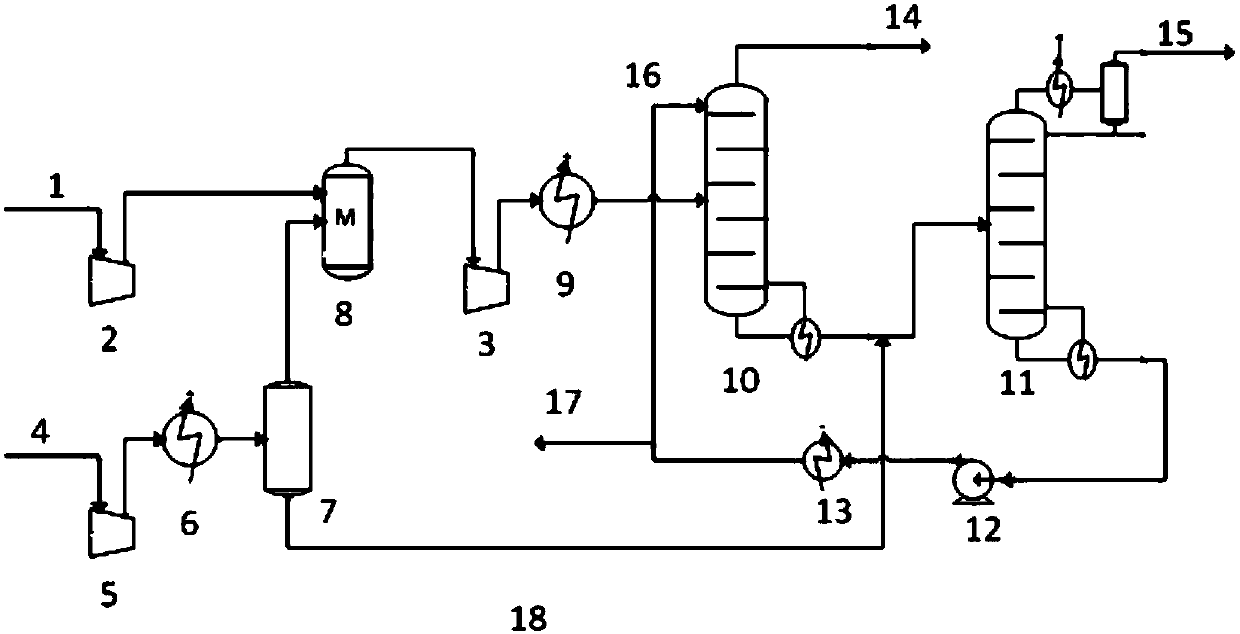
[0072] The dry gas (pressure 0.25MPaG) from the PX unit from the refinery aromatics complex is supplied to the aromatics dry gas compressor 5 to increase the pressure to 2.5MPaG. The pressurized dry gas is cooled to 15°C by the lithium bromide refrigerator 6, and the gas-liquid phase separation is carried out in the liquid separation tank 7, and the gas phase at the top of the liquid separation tank 7 is sent to the inter-stage buffer tank 8 of the coking dry gas compressor.

[0073] The coking dry gas 1 (pressure 0.80MPaG) from the delayed coking unit of the refinery is boosted to 2.0MPaG by the coking dry gas compressor section 2, and then supplied to the coking dry gas compressor section together with the gas phase at the top of the liquid separation tank 7 The gas phase at the top of the buffer tank 8 is boosted to 4.0MPaG through the...

Embodiment 2

[0079] This example is used to illustrate the method for recovering carbon dioxide in refinery dry gas according to the present invention.

[0080] The dry gas (pressure 0.25MPaG) from the PX unit from the refinery aromatics complex is supplied to the aromatics dry gas compressor 5 to increase the pressure to 4.5MPaG. The pressurized dry gas is cooled to 15°C by the lithium bromide refrigerator 6, and the gas-liquid phase separation is carried out in the liquid separation tank 7, and the gas phase at the top of the liquid separation tank 7 is sent to the inter-stage buffer tank 8 of the coking dry gas compressor.

[0081] The coking dry gas 1 (pressure 0.80MPaG) from the delayed coking unit of the refinery is boosted to 2.0MPaG by the first section 2 of the coking dry gas compressor, and then supplied to the coking dry gas compressor section together with the gas phase at the top of the liquid separation tank 7 The gas phase at the top of the buffer tank 8 is boosted to 5.0 MP...

Embodiment 3

[0087] This example is used to illustrate the method for recovering carbon dioxide in refinery dry gas according to the present invention.

[0088] The dry gas (pressure 0.25MPaG) from the PX unit from the refinery aromatics complex is supplied to the aromatics dry gas compressor 5 to increase the pressure to 3.0MPaG. The pressurized dry gas is cooled to 5°C by the lithium bromide refrigerator 6, and the gas-liquid phase separation is carried out in the liquid separation tank 7, and the gas phase at the top of the liquid separation tank 7 is sent to the inter-stage buffer tank 8 of the coking dry gas compressor.

[0089] The coking dry gas 1 (pressure 0.80MPaG) from the delayed coking unit of the refinery is boosted to 2.0MPaG by the coking dry gas compressor section 2, and then supplied to the coking dry gas compressor section together with the gas phase at the top of the liquid separation tank 7 The gas phase at the top of the buffer tank 8 is boosted to 3.5MPaG through the ...


PUM


Abstract

The invention relates to the field of dry gas treatment, and particularly discloses a method for recycling C-2 in dry gas of a refinery. The method includes: 1), subjecting aromatic hydrocarbon dry gas to compression treatment and cooling phase-splitting treatment sequentially; 2), feeding coked dry gas into a coked dry gas compressor for compression treatment, and a gaseous phase obtained throughcooling phase-splitting treatment into a segment or an outlet of a coked gas dry gas compressor; 3), cooling mixed dry gas gathering at the outlet of the coked dry gas compressor, and using C-4 fraction as an absorbing agent for absorbing treatment in an absorbing tower; 4), feeding a liquid phase obtained by cooling phase-splitting treatment in the step 1) and tower kettle material flow of the absorbing tower into a desorbing tower for desorbing treatment. The method is high in C-2 recycling rate, a propylene refrigerating system and a drying system are not needed, components above C-3 in product gas are low in content, and the method has the advantages of low energy consumption and little investment.

Description

technical field [0001] The invention relates to the field of dry gas treatment, in particular to a method for recovering carbon dioxide in refinery dry gas. Background technique [0002] Refinery dry gas, such as delayed coking unit dry gas, aromatics complex dry gas, etc., comes from the secondary processing of crude oil. Dry gas usually contains a large amount of ethane components, for example, the molar content of ethane in coking dry gas is about 10-24%, and the dry gas of aromatics complex, such as the molar content of ethane in the dry gas of PX unit is about 25-70% %. At present, refinery dry gas is mainly burned as fuel, and its utilization value is low. If the ethane component in the dry gas is concentrated and sent to the ethane cracking furnace of the ethylene plant as raw material, the economic and social benefits are very obvious. Since the cracking performance of the ethane component in the raw material of the ethane cracking furnace of the ethylene plant is...

Claims


Application Information

Patent Timeline
Patent Type & Authority Applications(China)
IPC IPC(8): C07C9/06C07C7/11C07C7/00
Inventor 邵华伟张敬升刘智信罗淑娟邹弋李东风
Owner CHINA PETROLEUM & CHEM CORP
Why Eureka
Try Eureka