An Arc Light Electron Source Assisted Ion Nitriding Process

A technology of ion nitriding and electron source, applied in metal material coating process, coating, solid-state diffusion coating, etc., can solve the problems of unsatisfactory green manufacturing concept, long nitriding process time, large gas consumption, etc., to achieve Effects of reduced energy consumption, wide processing temperature range, and reduced gas emissions

Active Publication Date: 2021-10-19
DONGGUAN HUICHENG VACUUM TECH
View PDF6 Cites 0 Cited by
  • Summary
  • Abstract
  • Description
  • Claims
  • Application Information

AI Technical Summary

Problems solved by technology

[0010] However, the existing ion nitriding glow discharge plasma is still relatively weak, and has disadvantages such as long nitriding process time, high energy consumption, and large gas consumption, and is not ideal for the concept of green manufacturing.

Method used


Image

  • An Arc Light Electron Source Assisted Ion Nitriding Process
  • An Arc Light Electron Source Assisted Ion Nitriding Process

Examples


Embodiment 1

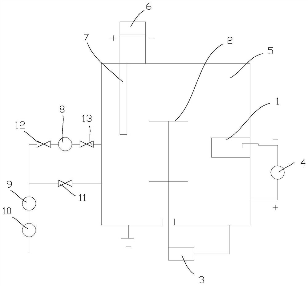
[0061] M2 high-speed steel ion nitriding process, using HC380 ion nitriding furnace, which is equipped with arc light electron source, using arc light electron source to assist high vacuum ion nitriding, the steps are as follows:

[0062] Pre-treatment of ion nitriding: Polish the M2 high-speed steel sample of HRC62-65 after heat treatment, then perform ultrasonic cleaning in alcohol for 10 minutes, fully dry and put it into the vacuum chamber of ion nitriding furnace.

[0063] Vacuuming: the background vacuum of the vacuum chamber is 3.0×10 -3 Pa;

[0064] 1) Preheating: Turn on the heater in the furnace, heat to 500°C, and keep warm for 60 minutes;

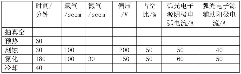
[0065] 2) Etching (enhanced cleaning of the arc light electron source): connect the two electrodes of the pulsed DC bias power supply, the anode is connected to the shell of the sealed container and grounded, and the cathode is connected to the sealed container and hung on the workpiece on the workpiece turret; Enter the argon...

Embodiment 2

[0069] 304 stainless steel ion nitriding process, using HC650 ion nitriding machine, using arc light electron source to assist nitriding preparation, the steps are as follows

[0070] Pre-treatment: Polish the 304 stainless steel sample and then ultrasonically clean it in alcohol for 10 minutes. After fully drying, put it into the vacuum chamber of the nitriding machine. The background vacuum of the vacuum chamber is 5.0×10 -3 Pa;

[0071] 1) Preheating: heat to 450°C and keep warm for 40 minutes;

[0072] 2) Etching: Enhanced cleaning of the arc electron source: Introduce argon gas, adjust the air pressure to 0.6Pa, turn on the arc electron source, turn on the main power supply of the arc electron source, adjust the current to 70A, turn on the arc electron source auxiliary anode power supply, and adjust the current to 40A, turn on the bias voltage and adjust the bias voltage to 300V, the duty cycle is 50%, and the ion cleaning is enhanced for 20 minutes;

[0073] 3) Nitridi...


PUM


Abstract

An arc electron source assisted ion nitriding process: S1. Vacuuming; S2. Preheating; S3. Etching: argon gas is introduced to maintain a vacuum of 0.1‑‑1Pa, the temperature is 200‑‑600°C, between the workpiece and the cavity Apply a bias voltage between them, and start the arc electron source in the furnace at the same time. The current of the main power supply is 40-150A to generate arc discharge plasma; turn on the auxiliary anode power supply with a current of 10-100A to guide the electron flow in the arc discharge plasma into the nitriding chamber space , perform ion bombardment etching on the workpiece for 5-30 minutes; S4. Nitriding: maintain the temperature in the furnace at 200-600°C, feed argon and nitrogen, keep the vacuum at 0.1-1Pa, and DC bias power supply between the workpiece and Apply voltage between the chambers, turn on the main power supply of the arc electron source, the current is 40‑150A, and generate arc discharge plasma; turn on the auxiliary anode power supply, and the current is 10‑100A, and guide the electron flow of the arc discharge plasma into the nitriding chamber space, and the ions Nitriding for 0.5-6 hours; S5. Cool to below 250°C. The invention can enhance glow discharge plasma, improve reaction activity, shorten time and reduce gas and energy consumption.

Description

technical field [0001] The invention relates to an ion nitriding process, in particular to an arc light electron source assisted ion nitriding process. Background technique [0002] The ion nitriding method is in a nitrogen-containing atmosphere of 13.33-1333Pa, with the furnace body as the anode and the workpiece to be processed as the cathode, and a DC voltage of several hundred volts is applied between the cathode and the anode. Photodischarge phenomenon, which produces soft light like neon lights covering the surface of the workpiece being processed. At this time, the ionized gas component is accelerated by the electric field, hits the surface of the workpiece to be processed to heat it, and at the same time relies on sputtering and nitrogen ions to bombard the surface of the workpiece to produce a nitriding reaction with it. This is called ion nitriding treatment. [0003] The ion nitriding method is completely different from the traditional method of nitriding by dec...

Claims


Application Information

Patent Timeline
Patent Type & Authority Patents(China)
IPC IPC(8): C23C8/38C23C8/02
Inventor 李迎春刘江江李志荣
Owner DONGGUAN HUICHENG VACUUM TECH
Why Eureka
Try Eureka