Submarine gas receiving facility with built-in heating pipe

A technology with built-in heating and receiving equipment, which is applied in the direction of mining fluid, earthwork drilling, reagents, etc., can solve problems such as natural gas leakage, achieve the effects of enhancing soil compactness, high safety and efficiency, and avoiding waste and environmental pollution

Active Publication Date: 2019-05-24
MARINE FISHERIES RES INST OF ZHEJIANG
View PDF5 Cites 3 Cited by
  • Summary
  • Abstract
  • Description
  • Claims
  • Application Information

AI Technical Summary

Problems solved by technology

[0004] The object of the present invention is to provide a seabed natural gas receiving equipment with a built-in heating pipeline, which overcomes the problem of natural gas leaking from the closed edge soil layer in the mining process of the closed cap layer, and has high safety and efficiency during the entire mining process, and is not easy to cause environmental pollution. Pollution, less equipment damage

Method used


Image

  • Submarine gas receiving facility with built-in heating pipe
  • Submarine gas receiving facility with built-in heating pipe
  • Submarine gas receiving facility with built-in heating pipe

Examples


Embodiment 1

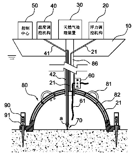
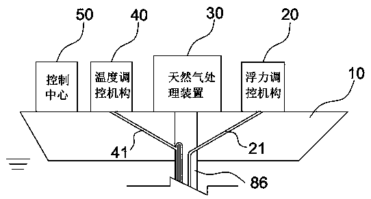
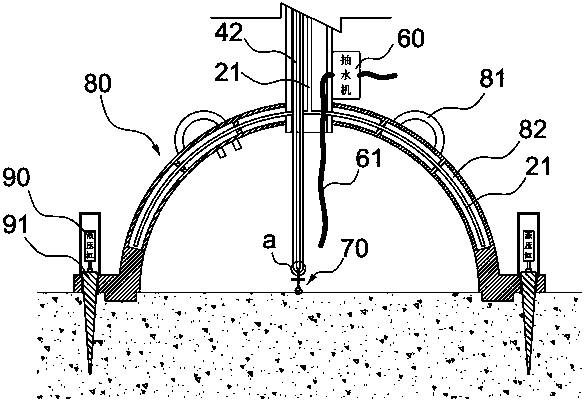
[0028] Such as Figure 1-6 As shown, the subsea natural gas receiving equipment with a built-in heating pipeline includes a gas collecting hood 80, which is connected to the natural gas processing device 30 on the hull 10 through a gas collecting pipe 86. The gas collecting hood 80 is a hemispherical hollow circular cover, and the gas collecting The side of the cover 80 is connected with a circular ring 83 on the same bottom surface. A hydraulic cylinder 90 that moves vertically up and down is surrounded on the circular ring 83. The output end of the hydraulic cylinder 90 is connected with an annular sealing body 91 that penetrates the circular ring 83. The sealing body 91 and the The area of ​​the contact end of the hydraulic cylinder 90 is smaller than the area of ​​the bottom end, and the bottom surface of the air collecting cover 80 inside the sealing body 91 is also provided with a protruding ring 84, and the protruding ring 84 is horizontally provided with through holes. ...

Embodiment 2

[0040] This embodiment further optimizes its technical scheme on the basis of Embodiment 1: a stirring mechanism 70 is connected to the bottom of the circulating pipe 42, and the stirring mechanism 70 includes a rotating shaft 71, and a rotating shaft 71 is vertically connected to the bottom end of the circulating pipe 42. Rotating blades 72 are set around the rotating shaft 71, the middle part of the rotating shaft 71 is provided with a supporting ring 73, the supporting ring 73 is horizontally connected with a supporting plate 74, and the surface of the supporting plate 74 is provided with a rectangular through hole, and one corner of the rectangular through hole is arc-shaped. The rest are right angles, and the bottom of the rotating shaft 71 is connected to the impeller 75 . The carbon dioxide gas flow flowing in the circulation pipe 42 is used to drive the rotating blade 72 to rotate, which saves the driving force for driving the rotating shaft 71 and saves energy consumpt...

Embodiment 3

[0042] The sealing body 91 of the present invention is prepared from rubber, and its specific preparation method is as follows:

[0043] Mixing: Take methyl vinyl silicone rubber raw rubber in parts by weight and put it into the open mill, slowly add fumed silica K-200, hydroxy silicone oil, and glyceryl caprylate during the open mill, and the whole process continues 0.5h, then continue to heat the ceramic filler, antimony hydroxide, silicon dioxide, high vinyl silicone oil and silane coupling agent, the whole process lasts for 0.5h, after the mixing is completed, the sheets are evenly produced;

[0044] High temperature treatment: Put the above compounded rubber in an electric blast drying oven at 178°C for 80 minutes, take it out and air cool for 24 hours;

[0045] Back refining: Put the cooled rubber compound after the above high-temperature treatment into the open mill again, add vulcanizing agent after 5 times of thinning, and continue thinning for 10 times to produce tab...


PUM


Abstract

The invention discloses a submarine gas receiving facility with a built-in heating pipe and belongs to the technical field of submarine gas extraction. The submarine gas receiving facility comprises ahemispherical hollow gas collecting hood, which is connected to a natural gas treatment device on a ship body through a gas collecting pipe. A circular ring sharing the same bottom surface with the gas collecting hood is connected to the lateral side of the gas collecting hood, a vertically moving hydraulic cylinder surrounds the circular ring, an annular sealing member penetrating through the circular ring is connected to the outer end of the hydraulic cylinder, the area of the contact end of the sealing member with the hydraulic cylinder is smaller than that of its bottom end, and a projecting ring is arranged on the bottom surface of the gas collecting hood on the inner side of the sealing member and is horizontally provided with a penetrating through hole. The submarine gas receivingfacility with the built-in heating pipe has the advantages that leakage of natural gas from sealed edge soil layers during caprock-sealing extraction is avoided, and the whole extraction process is safe, efficient, less prone to causing environmental pollution and small in equipment damage.

Description

technical field [0001] The invention belongs to the technical field of seabed natural gas collection, and in particular relates to a seabed natural gas receiving device with a built-in heating pipeline. Background technique [0002] Natural gas hydrate, also known as "combustible ice", is a "cage compound" formed by methane-based hydrocarbon gas and water under certain temperature and pressure conditions. It is a white solid substance with a density close to and slightly lower than that of Due to the density of ice, the discovered natural gas hydrates mainly exist in the permafrost areas in the Arctic region and in the seabed, continental slope, land base and trenches around the world. The types of storage layers mainly include sandstone, sandstone fracture, Fine-grained fracture type and dispersed type, and it usually exists in the seabed at a water depth of 300~3000m. Natural gas hydrates exist widely in the world. According to the evaluation results of relevant scientist...

Claims


Application Information

Patent Timeline
IPC IPC(8): E21B43/01E21B33/037E21B43/16C08L83/07C08L83/04C08K13/02C08K5/103C08K3/36C08K3/22
CPCY02P20/141
Inventor 卢占晖徐开达戴乾卢衎尔朱文斌
Owner MARINE FISHERIES RES INST OF ZHEJIANG
Why Eureka
Try Eureka