
Glow plasma generation device applied to surface modification of high polymer material

A polymer material and surface modification technology, which is applied in the fields of plasma, electrical components, ultrasonic/sonic fiber processing, etc., can solve the limitation of surface modification effect improvement, high cost of nanosecond pulse power supply, and increase of electron avalanche severity, etc. problems, to avoid thermal instability effects, do not damage the performance of the body, and be easy to apply on a large scale

Pending Publication Date: 2019-05-24
重庆中涪科瑞工业技术研究院有限公司
View PDF0 Cites 2 Cited by
  • Summary
  • Abstract
  • Description
  • Claims
  • Application Information

AI Technical Summary

Problems solved by technology

However, the nanosecond pulse power supply has problems such as high cost, large loss, and difficulty in increasing power, and it is also difficult to achieve large-scale industrialization
[0013] 2) The activity of plasma is still relatively low, which seriously limits the further improvement of its surface modification effect, and it is difficult to meet the requirements of aramid fiber in high-end application fields
However, a strong electric field will further increase the intensity of the development of electron avalanche, which will further increase the difficulty of glow discharge generation.

Method used


Image

  • Glow plasma generation device applied to surface modification of high polymer material
  • Glow plasma generation device applied to surface modification of high polymer material
  • Glow plasma generation device applied to surface modification of high polymer material

Examples


Embodiment 1

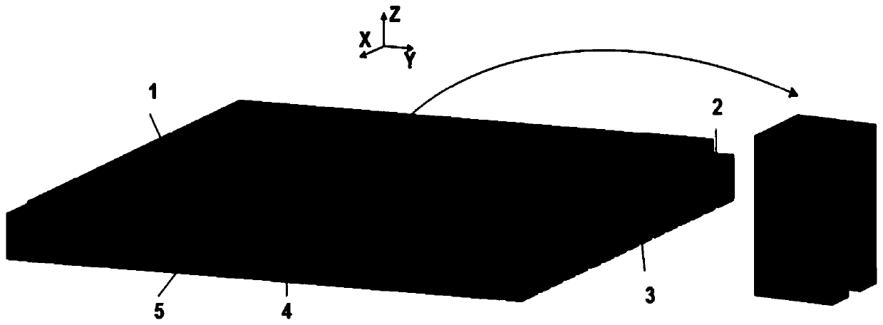
[0040] figure 1 It is a schematic structural diagram of a glow plasma generation device for surface modification of polymer materials provided by an embodiment of the present invention; figure 1 As shown, a glow discharge plasma generating device applied to the surface modification of polymer materials includes a high-voltage electrode 1, a high-voltage side insulating medium 2, a grounding electrode 3, a grounding side insulating medium 4, and a modified material 5; The upper surface of the high-voltage side insulating medium 2 is in close contact with the high-voltage electrode 1, and the lower surface of the high-voltage side insulating medium 2 is provided with several parallel and closely arranged grooves, the groove depth of which is less than 1mm; the ground electrode 3 is composed of a plurality of conductive wires, which are arranged in parallel and embedded in the ground-side insulating medium 4; the modified material 5 is placed between the high-voltage side insulat...

Embodiment 2

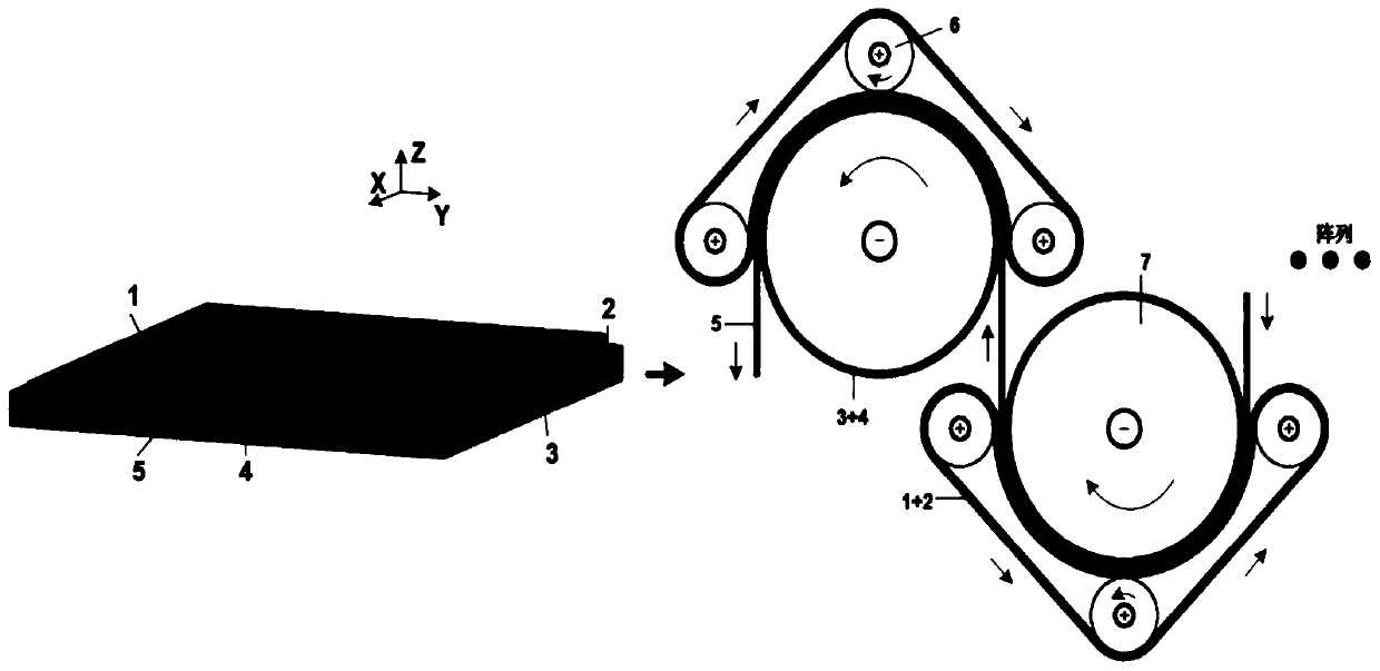
[0044] figure 2 It is a schematic structural diagram of another glow plasma generating device for surface modification of polymer materials provided by an embodiment of the present invention.

[0045] Such as figure 2 As shown, in the device provided in this embodiment, the high-voltage electrode is replaced by the metal flat electrode described in Embodiment 1 with a crawler type; the ground electrode is replaced by the flat electrode described in Embodiment 1 with a roller type; the crawler-type high-voltage electrode and the idler-type ground electrode constitute a set of modification devices.

[0046] Such as image 3 As shown, the crawler-type high-voltage electrode includes a high-voltage side conductive roller 6, a high-voltage side conductive track 1, and a high-voltage side insulating medium 2; the high-voltage side conductive roller 6 is used to support the high-voltage side conductive track 1 and the high-voltage side insulating medium 2. The high-voltage side ...


PUM

PropertyMeasurementUnit
depthaaaaaaaaaa
depthaaaaaaaaaa
widthaaaaaaaaaa

Abstract

The invention discloses a glow discharge plasma generation device applied to surface modification of a high polymer material. The glow discharge plasma generation device comprises a high-voltage electrode, a high-voltage side insulating medium, a grounding electrode, a grounding side insulating medium and a modified material. The upper surface of the high-voltage side insulating medium is tightlyattached to the high-voltage electrode, and the lower surface of the high-voltage side insulating medium is provided with a plurality of grooves which are tightly arranged in parallel. The grounding electrode is composed of a plurality of conductive wires, and the conductive wires are embedded into the grounding side insulating medium in parallel. The modified material is arranged between the high-voltage side insulating medium and the grounding side insulating medium. The high-voltage side insulating medium and the modified material are in close contact, and the modified material and the grounding side insulating medium are in close contact. The device is based on a tooth-shaped electrode structure, generates high-activity glow discharge plasma under the atmospheric pressure air condition, does not need vacuum and sealing equipment, has very high plasma activity and a dispersed discharge form, and has a very excellent modification effect.

Description

technical field [0001] The invention belongs to the technical field of gas discharge and surface modification of polymer materials, and mainly relates to a glow plasma generating device applied to the surface modification of polymer materials. Background technique [0002] The full name of aramid fiber is "polyphenylene phthalamide". As a new type of high-tech synthetic material, it is also known as the world's three major high-performance fibers together with carbon fiber and polyethylene fiber. It is the composite material with the most development potential. Reinforcement material. It has many advantages such as high mechanical strength, good toughness, light weight, low dielectric constant, high temperature resistance, good wear resistance, and stable chemical properties. Its mechanical strength is 5-6 times that of steel wire, its modulus is 2-3 times that of steel wire or glass fiber, its toughness is 2 times that of steel wire, and its weight is only about 1 / 5 of tha...

Claims


Application Information

Patent Timeline
Patent Type & Authority Applications(China)
IPC IPC(8): H05H1/46D06M10/02
Inventor 刘文正陈晓中
Owner 重庆中涪科瑞工业技术研究院有限公司
Learn More