Supercharge Your Innovation With Domain-Expert AI Agents!

A Mechanical Cryo-Trap Based on Moving Parts

A low-temperature cold trap and moving parts technology, applied in mechanical equipment, machines/engines, liquid variable capacity machinery, etc., can solve the problems of large energy consumption and heat leakage, low cooling and heating efficiency, bulky volume, etc., to reduce leakage Effect of heat loss and improvement of heating efficiency and enrichment efficiency

Active Publication Date: 2021-05-25
杭州阿卡米低温科技有限责任公司 +1
View PDF8 Cites 2 Cited by
  • Summary
  • Abstract
  • Description
  • Claims
  • Application Information

AI Technical Summary

Problems solved by technology

[0008] At present, cascade coke-soup refrigerators are generally chosen to provide ultra-low temperature cold sources for cryogenic traps, but this method has relatively large limitations.
First of all, the coke soup refrigerator has a high cooling efficiency in the general cold temperature zone, but this kind of refrigerator needs to obtain a lower cooling temperature through a multi-stage cascading method, resulting in low cooling efficiency, high energy consumption and large volume
Secondly, due to the large span of the refrigeration temperature range, it is often necessary to use composite refrigerants to obtain extremely low temperatures below -150°C. A slight leak of the composite refrigerant can cause the refrigerator to fail, which will undoubtedly increase the difficulty of operation.
[0009] In short, the -150°C low-temperature cold trap products on the market are currently scarce, and the existing products all use the self-cascading refrigeration method to provide the cold source, which is bulky, high energy consumption, and has major deficiencies.
[0010] In addition, the current structure of the cryogenic cold trap adopts a static mechanism, that is, no matter in the low temperature mode or in the high temperature mode, the distance and position of the drying tube and the enrichment tube relative to the cold head are unchanged. As a result, when the two modes work alternately, the energy consumption and heat leakage are large, and the cooling or heating efficiency is low

Method used


Image

  • A Mechanical Cryo-Trap Based on Moving Parts
  • A Mechanical Cryo-Trap Based on Moving Parts
  • A Mechanical Cryo-Trap Based on Moving Parts

Examples


Embodiment Construction

[0038] The present invention will be further described below in conjunction with accompanying drawing:

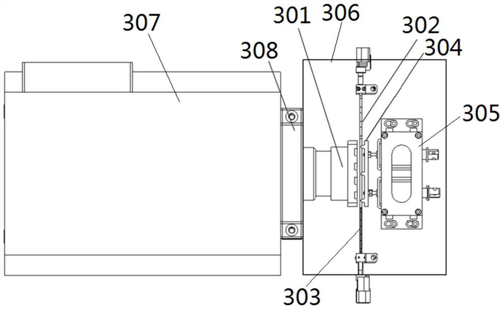
[0039] Such as image 3 and Figure 4 As shown, a mechanical cryogenic cold trap based on moving parts includes: cold head 301 , drying pipe 302 , enrichment pipe 303 , manipulator 304 , electric cylinder 305 and vacuum cover 306 . The cold head 301 , the drying pipe 302 , the enrichment pipe 303 , the manipulator 304 , and the electric cylinder 305 are all arranged in the vacuum cover 306 .

[0040] The cold head 301 uses the Stirling refrigerator 307 to provide a cold source, and the cold head of the existing Stirling refrigerator can be directly used. The Stirling refrigerator 307 is hermetically connected with the vacuum cover 306 through a vacuum flange 308 . The cold head 301 can directly use a copper block, and the cooling surface has a plate structure, which is convenient for cooling the drying pipe 302 and the enrichment pipe 303 .

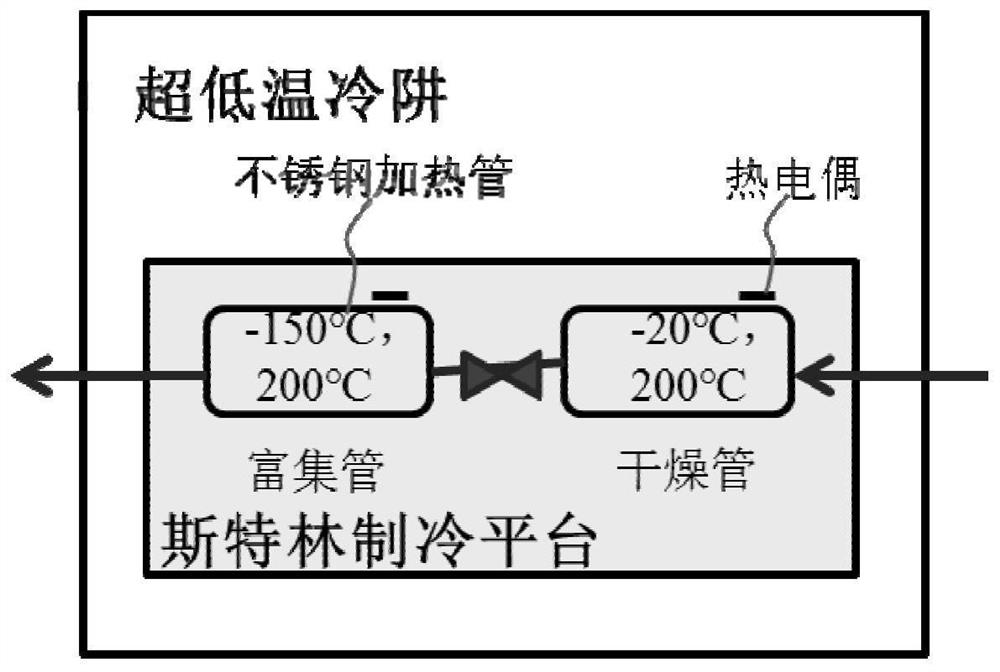
[0041] Both the drying tube...


PUM


Abstract

The invention discloses a mechanical low-temperature cold trap based on moving parts, including: a cold head; an elastic drying tube and an enrichment tube; Push the tube to the cold head and keep the drying tube and the enrichment tube in the first working position of this position, and when the cryogenic cold trap is in the high temperature mode, release the drying tube and the enrichment tube in the second working position; When the cryogenic cold trap is in the high temperature mode, there is a gap between the drying pipe, the enrichment pipe and the cold head. In the present invention, by setting the moving parts, the position of the drying tube and the enrichment tube relative to the cold head of the cryogenic cold trap can be changed in real time under different working modes, which reduces the heat leakage loss and the heat load of the refrigerator, and improves the energy efficiency of the cold head and the enrichment efficiency of the cryogenic cold trap.

Description

technical field [0001] The invention belongs to the technical field of low temperature cold trap design, in particular to a mechanical low temperature cold trap based on moving parts. Background technique [0002] In recent years, with the emphasis on air pollution control, especially urban smog control, the monitoring and control of subdivided pollutants such as volatile organic compounds (VOCs) have also been frequently put on the agenda. VOCs (volatile organic compounds) refer to organic compounds with a saturated vapor pressure greater than 70Pa at normal temperature and a boiling point below 260°C at normal pressure. However, the VOCs monitoring link is weak and the method system is not perfect, which affects the implementation of VOCs governance work and the effective supervision of governance facilities. Relevant experts suggest that in the near future, the country should further increase investment in research and development of detection and analysis equipment, and...

Claims


Application Information

Patent Timeline
Patent Type & Authority Patents(China)
IPC IPC(8): B01D8/00
Inventor 甘智华
Owner 杭州阿卡米低温科技有限责任公司
Features
  • R&D
  • Intellectual Property
  • Life Sciences
  • Materials
  • Tech Scout
  • Unparalleled Data Quality
  • Higher Quality Content
  • 60% Fewer Hallucinations
Learn More