Metal cutting machining system

A processing system and metal cutting technology, applied in metal processing, metal processing equipment, metal processing mechanical parts, etc., can solve the problems of unsatisfactory cooling performance, lack of cooling, unstable tool operation, etc., to achieve good dynamic follow performance and resistance Interfere with performance, reduce inaccuracies in accuracy, reduce waste in efficiency

Active Publication Date: 2019-05-28
QINGDAO UNIV
View PDF13 Cites 9 Cited by
  • Summary
  • Abstract
  • Description
  • Claims
  • Application Information

AI Technical Summary

Problems solved by technology

[0004] The current processing equipment has insufficient machining accuracy, unstable tool operation, lack of precise feedback control of the servo mo

Method used


Image

  • Metal cutting machining system
  • Metal cutting machining system
  • Metal cutting machining system

Examples


Embodiment Construction

[0022] The present invention will be further described below in conjunction with the accompanying drawings and embodiments.

[0023] Embodiments of the Invention References Figure 1-6 shown.

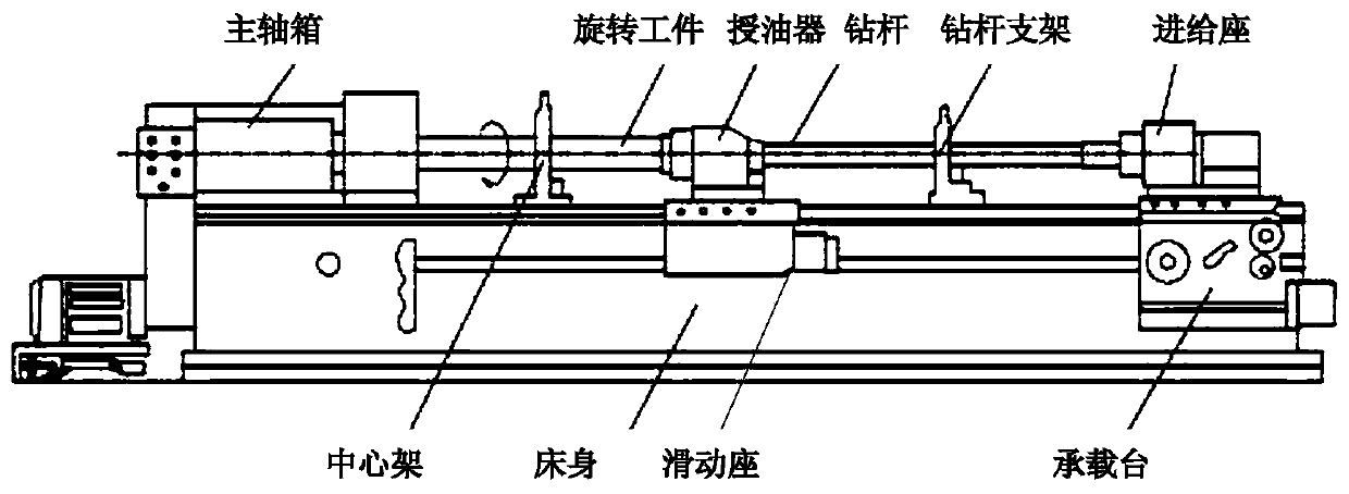
[0024] A metal cutting processing system, which includes a workbench, drive control equipment, chatter detection equipment, circulation equipment,

[0025] The workbench includes spindle box, rotating workpiece, oiler, drill pipe, drill pipe support, feed seat, bearing table, bed, center frame, sliding seat, and the left end of the rotating workpiece is installed in the three-jaw chuck of the spindle box , the right end of which is close to the oiler, and the rotating workpiece is supported by the center frame to increase the rigidity and ensure the coaxiality of the parts. The shank of the drill pipe is clamped in the positioning hole of the feed seat, and the drill pipe is installed in the middle of the drill pipe. Supported by the bracket, the oil feeder sends high-pressure cutting...


PUM


Abstract

The invention relates to a metal cutting machining system. The metal cutting machining system comprises a workbench, driving control equipment, flutter detection equipment and circulating equipment. The workbench comprises an oil feeding device, a main shaft box, a rotary workpiece, a drill rod, a drill rod support, a feeding seat, a bearing table, a machine tool body, a center frame and a slidingseat. The driving control equipment comprises a motion controller, an encoder, a Hall current sensor, a decoding circuit, an optical coupling isolation circuit, a servo motor and an intelligent powercontrol module. A target position, an actual position and actual current are subjected to single-axis logic control in the motion controller. A pulse width modulation signal is output through the time sequence regulation of vector control. The flutter detection equipment comprises an industrial personal computer, a vibration sensor and an audio sensor. The vibration sensor and the audio sensor are arranged on the feeding seat of the workbench so as to measure mechanical vibration signals and noise signals of cutter cutting and transmit the mechanical vibration signals and the noise signals tothe industrial personal computer. The industrial personal computer judges whether cutting is normal or not according to the mechanical vibration signals and the noise signals.

Description

technical field [0001] The present application relates to a processing system, especially a metal cutting processing system. Background technique [0002] The demand for deep hole processing technology can be traced back to the advent of European sliding chamber guns (14th century), but it was not until the first half of the 20th century that deep hole processing technology came out. In the late 18th century, people invented the flat drill to process more precise barrels. The flat drill is the oldest solid drilling tool. It has been used for a long time to process short and shallow holes in wood, iron, bronze, etc. It has been continuously improved and is still used to process single-piece small batches of deep-hole parts. However, in the process of deep-hole processing, due to the existence of its chisel edge and the limitations of cutting edges, the processing efficiency is extremely low and continuous processing is not possible. Processing, the drill bit is easy to go of...

Claims


Application Information

Patent Timeline
IPC IPC(8): B23Q37/00B23Q5/40B23Q15/00B23Q11/00B23Q11/10
Inventor 王怀志谷正李培耀王立
Owner QINGDAO UNIV
Why Eureka
Try Eureka