Peak pulse sampling device and method for laser ranging system

A spike pulse and laser ranging technology, applied in the field of laser measurement, can solve the problems of mass data transmission, high power consumption, high cost, etc., and achieve the effect of improving sampling accuracy, high cost, and reducing processing power consumption

Inactive Publication Date: 2019-05-28
北京跟踪与通信技术研究所 +1
View PDF6 Cites 1 Cited by
  • Summary
  • Abstract
  • Description
  • Claims
  • Application Information

AI Technical Summary

Problems solved by technology

[0004] The purpose of the present invention is to solve the problems of large power consumption, high cost, mass data transmission and other problems caused by the sampling of the laser ranging system, and provide a spike sampling device and method for the laser ranging system, which can realize the peak pulse High-precision sampling reduces the amount of data stored and transmitted, significantly reduces hardware resource consumption, reduces processing power consumption, and saves hardware costs

Method used


Image

  • Peak pulse sampling device and method for laser ranging system
  • Peak pulse sampling device and method for laser ranging system
  • Peak pulse sampling device and method for laser ranging system

Examples


Embodiment 1

[0036] Taking 20GHz sampling rate, 16 channels (N=16) pulse position modulation (PPM) signals, and a signal processing module equipped with FPGA as an example, the specific implementation process of the present invention will be described.

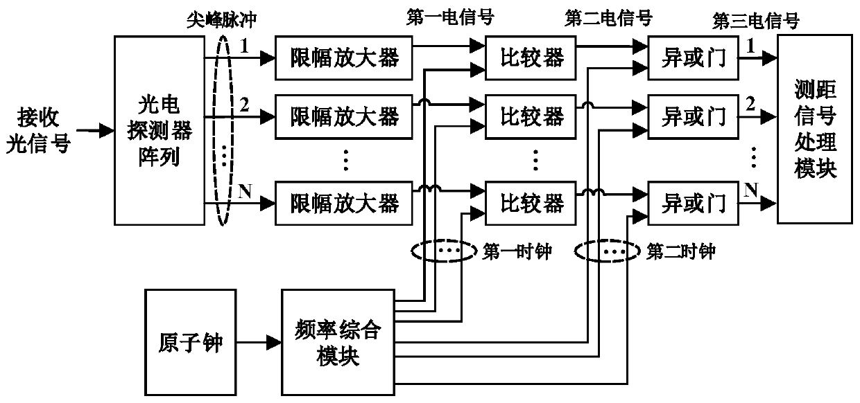
[0037] like figure 1 As shown, a spike sampling device for a laser ranging system disclosed in this embodiment includes a photodetector array, 16 limiting amplifiers, an atomic clock, a frequency synthesis module, 16 comparators, and 16 XOR gates and ranging signal processing module. The photodetector array is respectively connected with 16 limiting amplifiers, each limiting amplifier is connected with a corresponding comparator, the corresponding comparator is connected with a corresponding XOR gate, and the 16 XOR gates are respectively connected with the ranging signal processing module. The atomic clock is connected to the frequency synthesis module, and the frequency synthesis module is respectively connected to 16 comparators and 16...

Embodiment 2

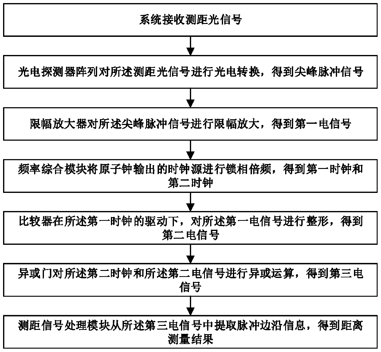
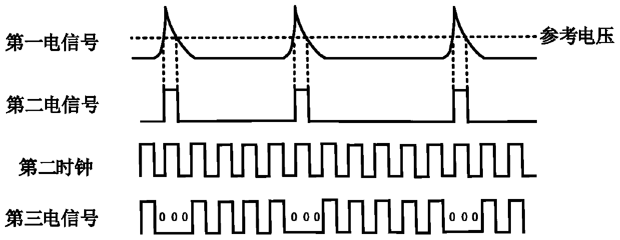
[0050] like figure 2 As shown, based on the above-described spike sampling device for a laser ranging system, this embodiment also discloses a spike sampling method for a laser ranging system. The distance optical signal first needs to undergo photoelectric conversion through the photodetector array to obtain a spike pulse signal, and then the limiting amplifier amplifies the signal level, improves the signal level, and suppresses excessive burrs; then the frequency synthesis module outputs the atomic clock. The clock source is phase-locked and frequency-multiplied to obtain the first clock and the second clock; further, the comparator shapes the first electrical signal to output a square wave; the XOR gate is used to obtain pulse edge information, and the three consecutive clocks are low power The pulse edge can be judged if it is even; finally, the signal processing module outputs the distance measurement result.

Embodiment 3

[0052] Taking 20GHz sampling rate, 16 channels (N=16) pulse position modulation (PPM) signals, and a signal processing module equipped with FPGA as an example, the specific implementation process of the present invention will be described.

[0053] Based on the described spike sampling device for laser ranging system, such as figure 2 As shown, this embodiment also discloses a spike sampling method for a laser ranging system, and the specific implementation steps are as follows:

[0054] Step 1. The 4×4 photodetector array photoelectrically converts the ranging optical signal, and outputs 16 channels of 20GHz single-ended spike pulse signals;

[0055] Step 2: Amplify the level of each pulse signal obtained in step 1 through the limiter amplifier HMC750 chip, so that the pulse signal reaches a level amplitude suitable for sampling, and obtains the first electrical signal. It should be noted that the single-ended spike signal is a 16PPM pulse signal, that is, 16 time slots are u...


PUM


Abstract

The invention discloses a peak pulse sampling device and method for a laser ranging system, and belongs to the field of laser measurement. The peak pulse sampling device for the laser ranging system comprises a photodetector array, N limiting amplifiers, an atomic clock, a frequency synthesis module, N comparators, N exclusive-or gates and a ranging signal processing module. The invention furtherdiscloses the peak pulse sampling method for the laser ranging system based on the peak pulse sampling device. According to the method, an analog signal is subjected to single-bit sampling quantization through the comparators and the exclusive-or gates, and edge information of peak pulses is extracted and used for ranging signal processing. By means of the peak pulse sampling device and method forthe laser ranging system, high-precision sampling of the peak pulses can be achieved, the data storage and transmission amount is reduced, the hardware resource consumption is significantly reduced,and the processing power consumption and the hardware cost are reduced; the sampling quality can be compensated for with a high sampling rate, and the sampling precision is improved.

Description

technical field [0001] The invention relates to a spike pulse sampling device and method, in particular to a spike pulse sampling device and method used in a laser ranging system, and belongs to the field of laser measurement. Background technique [0002] Laser ranging technology has the advantages of strong directionality, high measurement accuracy, and strong anti-electromagnetic interference ability. [0003] The spike receiving and processing technology is the core of the laser ranging system. For the analog pulse signal in the laser ranging system, it needs to be sampled and quantized before it can be converted into a digital signal that can be processed. With the continuous improvement of people's demand for ranging accuracy, the bandwidth of the pulse signal that needs to be processed also increases. As we all know, the sampling of band-limited signals should follow the Nyquist sampling theorem, that is, the sampling frequency is greater than twice the highest freq...

Claims


Application Information

Patent Timeline
Patent Type & Authority Applications(China)
IPC IPC(8): G01S7/486G01S17/10
Inventor 朱宏权邢强林孙亮亮雷呈强韩航程林玉洁马永锋刘家豪
Owner 北京跟踪与通信技术研究所
Why Eureka
Try Eureka