Organic light-emitting diode

An electroluminescent device and electroluminescent technology, applied in organic semiconductor devices, electric solid state devices, organic chemistry, etc., can solve triplet-polaron annihilation, low crossover rate between inverse systems, large energy level difference, etc. problems, to achieve the effect of controlling the difficulty of the evaporation process, improving the life of the device, and reducing the degree of overlap

Active Publication Date: 2019-06-18
KUNSHAN GO VISIONOX OPTO ELECTRONICS CO LTD +1
View PDF3 Cites 4 Cited by
  • Summary
  • Abstract
  • Description
  • Claims
  • Application Information

AI Technical Summary

Problems solved by technology

However, the current exciplex-type thermally activated delayed fluorescence (TADF) host materials have an energy level difference between singlet and t

Method used


Image

  • Organic light-emitting diode
  • Organic light-emitting diode
  • Organic light-emitting diode

Examples


Embodiment 1

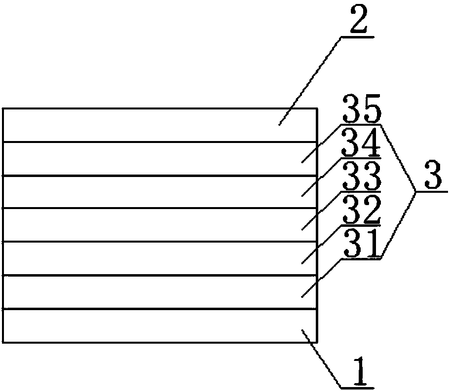
[0056] This embodiment provides an organic electroluminescent device, such as figure 2 As shown, there are a first electrode 1 , a second electrode 2 and an organic functional layer 3 between the first electrode 1 and the second electrode 2 . The first electrode 1 is an anode, the second electrode 2 is a cathode, and the organic functional layer 3 includes a stacked hole injection layer 31, a hole transport layer 32, a light emitting layer 33, an electron transport layer 34 and an electron injection layer 35, that is, the The structure of the organic electroluminescent device is: anode / hole injection layer / hole transport layer / light emitting layer / electron transport layer / electron injection layer / cathode.

[0057] The light emitting layer 33 is composed of a host material and a guest material doped in the host material. The guest material can be a fluorescent material or a phosphorescent material. Wherein, the exciplex is used as the host material, and the mass ratio of the...

Embodiment 2

[0073] In embodiment 2, the OLED device can be designed as the following organic electroluminescent device, the structure of the organic electroluminescent device includes an anode, a hole injection layer, a hole transport layer, an organic light emitting layer, an electron transport layer, an electron injection layer and the cathode. In this embodiment, a compound composed of triphenylamine and carbazolyl is selected as the donor molecule, and the selected substituent group X is Has the structure shown in formula (1-1):

[0074]

[0075] A compound composed of carbazolyl and triazinyl is selected as the acceptor molecule, which has the structure of formula (A), and the difference from the molecule (2-34) used in Example 1 is that there is no large steric hindrance substituting group tert-butyl, Formula (A) molecular structure:

[0076]

[0077] The donor molecule shown in formula (1-1) and the acceptor molecule shown in formula (A) constitute an exciplex, and in the ...

Embodiment 3

[0089] In embodiment 3, the OLED device can be designed as the following organic electroluminescent device, the structure of the organic electroluminescent device includes an anode, a hole injection layer, a hole transport layer, an organic light emitting layer, an electron transport layer, an electron injection layer and the cathode. In the present embodiment, the compound composed of triphenylamine group and carbazole group is selected as the donor molecule, and the selected steric hindering group X is Has the structure shown in formula (1-10):

[0090]

[0091] A compound composed of pyridyl and triazine is selected as the acceptor molecule, and the selected hindering group X is Has the formula (2-19) structure:

[0092]

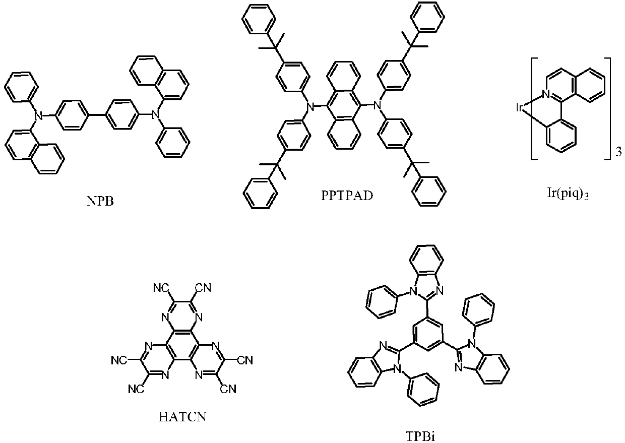
[0093] In embodiment 3, the first electrode in the organic electroluminescent device, that is, the anode, is made of ITO material; the hole injection layer is made of 2,3,6,7,10,11-hexacyano-1,4,5,8 , 9,12-hexaazatriphenylene (abbreviation: HAT...


PUM


Abstract

The invention belongs to the technical field of display, and specifically discloses an organic light-emitting diode. The organic light-emitting diode is provided with a first electrode, a second electrode, and an organic functional layer; the organic functional layer comprises a luminescent layer; the luminescent layer includes at least a host material and a guest material; the host material includes an exciplex composed of donor molecules and acceptor molecules; wherein the donor molecule and/or the acceptor molecule contain/contains a large steric hindrance substituent group X for increasingthe inter-molecular spacing between the donor molecule and the acceptor molecule, which can reduce the track overlap degree of HOMO and LUMO of the formed exciplex main body, reduce the singlet state-triplet state energy level difference [Delta]EST, improve the reverse intersystem crossing rate (kRISC) of the exciplex main body, enhance the energy transfer to the guest material molecules, and improve the device efficiency; meanwhile, the introduction of the large steric hindrance group can effectively reduce the triplet state concentration in the luminescent layer, inhibit the triplet state polaron annihilation (TPA), and improve the device lifetime.

Description

technical field [0001] The invention belongs to the field of display technology, and in particular relates to an organic electroluminescent device. Background technique [0002] Organic light-emitting diodes (OLEDs) have great application prospects in the fields of display and lighting due to their ultra-thin, light weight, low energy consumption, active light emission, wide viewing angle, and fast response. more and more people's attention. [0003] In 1987, Deng Qingyun (C.W.Tang) and Vanslyke of Eastman Kodak Company in the United States reported for the first time the use of transparent conductive films as anodes, Alq 3 As a light-emitting layer, a triarylamine material as a hole-transporting layer, and a Mg / Ag alloy as a cathode, a double-layer organic electroluminescent device is made. Traditional fluorescent materials are easy to synthesize, stable, and have a long device life. However, due to electron spin prohibition, only 25% of the singlet excitons can be used t...

Claims


Application Information

Patent Timeline
IPC IPC(8): H01L51/50
CPCC09K11/06C07D209/86C07D401/14C07D403/10H10K59/00H10K85/636H10K85/631H10K85/654H10K85/322H10K85/342H10K85/40H10K50/121H10K50/11H10K2101/10H10K2101/90C07F7/0812C09K2211/1018H10K85/633H10K85/6572H10K85/626H10K2101/30
Inventor 段炼宋晓增张东东李国孟
Owner KUNSHAN GO VISIONOX OPTO ELECTRONICS CO LTD
Why Eureka
Try Eureka