Polarized optic-acoustic microscopic imaging device and method

A technology of microscopic imaging and polarized light, which is applied in the direction of measuring devices, material analysis through optical means, instruments, etc., can solve the problems of polarization signal loss, etc., and achieve the effect of simple structure, convenient use, and easy industrialization

Inactive Publication Date: 2019-06-28
SOUTH CHINA NORMAL UNIVERSITY
View PDF5 Cites 6 Cited by
  • Summary
  • Abstract
  • Description
  • Claims
  • Application Information

AI Technical Summary

Problems solved by technology

However, polarized light microscopy remains challenging for biomedical applications due to extensive loss of polarization signals due to multiple scattering of the beam in biological tissue, and the complex understanding of tissue polarization measurements requires the development of a new technique, Enables three-dimensional high-contrast imaging of the microstructure of deep media

Method used


Image

  • Polarized optic-acoustic microscopic imaging device and method
  • Polarized optic-acoustic microscopic imaging device and method
  • Polarized optic-acoustic microscopic imaging device and method

Examples


Embodiment 1

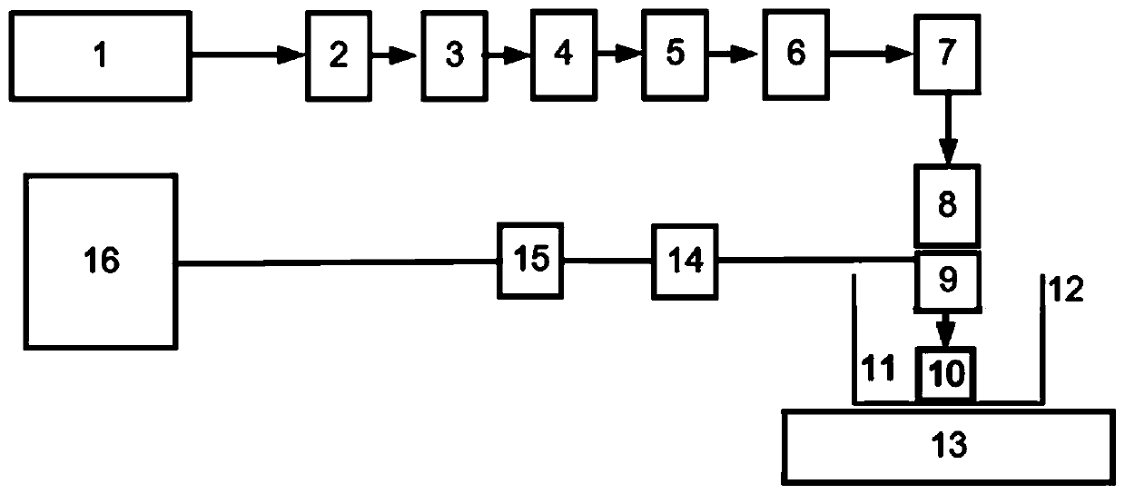
[0046] In this embodiment, a polarized photoacoustic microscopy imaging device is provided, such as figure 1As shown, it includes a photoacoustic excitation light source generation component, a photoacoustic signal processing component, and an acquisition platform component. The photoacoustic excitation light source generation component includes a laser 1, a first lens 2, a pinhole 3, a second lens 4, and a polarizer 5. One-half glass slide 6, scanning galvanometer 7 and focusing lens 8; the laser 1 is used to generate a laser beam, and the laser beam passes through the first lens 2, pinhole 3, second lens 4, and polarizer in sequence 5. Form linearly polarized light after 1 / 2 glass slide 6, scanning galvanometer 7 and focusing lens 8, and described pinhole 3 is arranged at the confocal place of first lens 2 and second lens 4; Said focusing lens 8 for focusing linearly polarized light on a sample 10 that generates a photoacoustic signal;

[0047] In this embodiment, the colle...

Embodiment 2

[0076] The technical solution of this embodiment 2 is except the following technical features, and other technical solutions are identical with embodiment 1:

[0077] In this embodiment, PVC (polyvinyl chloride), PVA (polyvinyl alcohol), 1% agar and 1% fat emulsion are used to make samples for polarized photoacoustic microscopic three-dimensional imaging and order three-dimensional imaging, mainly including the following steps:

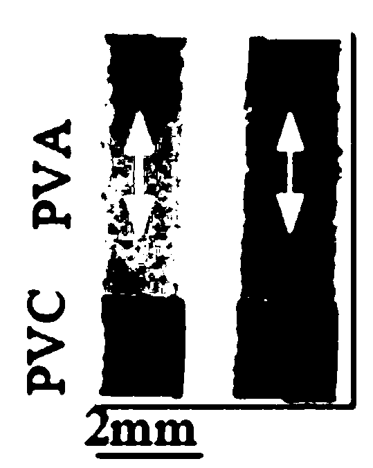
[0078] (1) Add 1% fat emulsion solution in the agar that concentration is 10g / L, and dip PVC (polyvinyl chloride), PVA (polyvinyl alcohol) obliquely into wherein and make experimental sample, as Figure 5 , where the white double-headed arrow represents the direction of the optical axis of the sample;

[0079] (2) Place the coupling tank 12 on the X-Y two-dimensional scanning platform of the stepping motor, fill in an appropriate amount of ultrasonic coupling liquid 11, immerse the sample 10 in the coupling tank 12, place the focusing lens 8 and the u...


PUM

PropertyMeasurementUnit
diameteraaaaaaaaaa

Abstract

The invention discloses a polarized optic-acoustic microscopic imaging device and method. The device comprises an optic-acoustic excitation light source generation assembly, an optic-acoustic signal processing assembly and a collection platform assembly; and the optic-acoustic excitation light source generation assembly comprises a laser, a first lens, a pin hole, a second lens, a polarizer, a 1/2glass slide, a scanning vibrating mirror and a focusing lens. The method comprises the concrete steps that the laser generates a laser beam, the laser beam passes the first lens, pin hole, second lens, polarizer, 1/2 glass slide, scanning vibrating mirror and focusing lens successively and forms linearly polarized light, the focusing lens focuses the linearly polarized light on a sample to generate an optic-acoustic signal, and the optic-acoustic signal processing assembly reconstructs a sample polarized optic-acoustic and quantitative ordered-degree 3D imaging graph according to optic-acoustic signals, generated by linearly polarized light in different electric vector direction, collected by the collection platform assembly and a medium ordered degree representing parameter. Thus, lossless high-definition 3D polarized light optic-acoustic microscopic imaging and quantitative structured ordered degree imaging can be realized.

Description

technical field [0001] The invention relates to the fields of material detection and imaging, in particular to a polarized photoacoustic microscopic imaging device and an imaging method. Background technique [0002] In the field of biomedical optics and materials inspection, polarized light microscopy is widely used as a non-invasive method to examine the microscopic properties of media. Using the depolarization behavior of incident polarized light interacting with the medium to obtain its unique optical properties and structural features, this behavior is sensitive to the subwavelength microstructure of the medium, such as the orientation and arrangement of scattering particles. However, polarized light microscopy remains challenging for biomedical applications due to extensive loss of polarization signals due to multiple scattering of the beam in biological tissue, and the complex understanding of tissue polarization measurements requires the development of a new techniqu...

Claims


Application Information

Patent Timeline
Patent Type & Authority Applications(China)
IPC IPC(8): G01N21/17G01N21/21
Inventor 石玉娇张振辉邢达
Owner SOUTH CHINA NORMAL UNIVERSITY
Why Eureka
Try Eureka