
Classified identification and positioning of metal workpiece welding defects based on fluorescent magnetic powder

A technology for fluorescent magnetic powder and metal workpieces, applied in the direction of material magnetic variables, etc., can solve problems such as complex procedures, high detection costs, and difficulty in realization

Inactive Publication Date: 2019-07-09
SOUTHWEAT UNIV OF SCI & TECH
View PDF6 Cites 8 Cited by
  • Summary
  • Abstract
  • Description
  • Claims
  • Application Information

AI Technical Summary

Problems solved by technology

New methods of welding skills are constantly emerging, and professional welding technology is also developing in the direction of digitalization and intelligence. The traditional human eye judgment can no longer meet the needs of social development, and there are many defects
[0003] Due to the continuous development of detection technology and intelligent technology, people began to explore some automatic detection methods. Some people used statistical analysis methods to study welding defects through the characteristics of random uncertainty in welding defects, and established a system based on statistics. On-line detection method of welding defects based on scientific method, some people have proposed online detection method of welding defects based on ray detection and ultrasonic detection technology, and some people have proposed based on wavelet theory, etc., although these methods have promoted detection technology However, there are also some shortcomings of their own: high detection cost, complicated process, low detection efficiency, difficult to realize automation, etc.
Fuzzy logic has the ability to imitate human thinking. On this basis, the fuzzy neural network produced by the combination of fuzzy logic and neural network has made a lot of progress in welding process control and welding defect identification. There are self-organizing feature maps (SCM) in China. ) The neural network automatically detects welding defects in the GTAW process. By observing the distribution characteristics of the probability density of parameters in each time interval during the welding process, it is possible to identify whether the defect corresponding to the weld position occurs according to the distribution of the electrical parameter histogram. In the case of no information provided Next, by selecting the appropriate number of output nodes, the automatic classification can be realized, and the stable signal can be completely separated. The wavelet transform analysis method can also be used to extract the sound wave energy in different frequency bands as the feature vector representing the size of the splash. The feature vector is established through the neural network model to the splash Quantity mapping model, so that the CO 2 Welding spatter is predicted, and the results show that the use of arc sound wave signals can accurately predict welding spatter, which is a new way to realize online control of welding quality, and realizes online automatic real-time control of the welding process. Using neural network technology can save a lot of work. The results that meet the requirements can be obtained through the experiment. When studying the detection of welding defects abroad, the X-ray pictures based on the neural network are processed to extract the defect features, and then the SVM "one-to-one" aggregation is established according to the characteristics of the weld defect samples. Class structure to identify samples, or use decision tree and fuzzy matrix to identify, can also obtain good identification and classification results, but X-ray itself is harmful to the human body, and the scope of use is also limited, so it is difficult to be widely used in industrialization detection

Method used


Image

  • Classified identification and positioning of metal workpiece welding defects based on fluorescent magnetic powder
  • Classified identification and positioning of metal workpiece welding defects based on fluorescent magnetic powder
  • Classified identification and positioning of metal workpiece welding defects based on fluorescent magnetic powder

Examples


Embodiment Construction

[0010] The technical solutions of the present invention will be further described in detail below in conjunction with the accompanying drawings and specific embodiments.

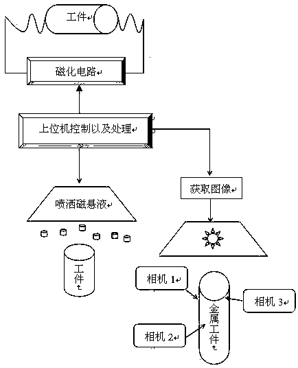
[0011] , The structure diagram used in this paper is as follows figure 1 As shown, it is mainly divided into four parts: the automatic magnetization device for grabbing workpieces, the spraying and recovery of magnetic suspension liquid, the online collection of magnetic trace images, and the processing and identification of computer software.

[0012] , Automatic magnetization device for grabbing workpieces

[0013] The manipulator picks up the workpiece from the workpiece groove and places it on the fixed magnetized contact. When the movable magnetized contact is extended to touch the top of the workpiece, the magnetization circuit starts to magnetize the workpiece horizontally and vertically. After the magnetization is completed, the movable magnetized contact retracts to its original position. The m...


PUM


Abstract

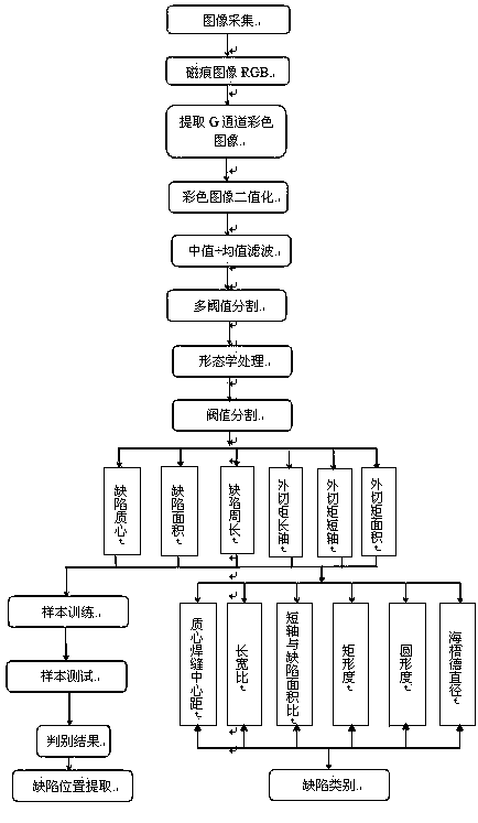
magnetic powder inspection is widely used in bearing welding crack detection, but the defect still requires manually visual inspection. In view of longitudinal welding defects (such as cracks, pores,slag inclusion or the like) generated by a metal workpiece in a welding process, a magnetic mark image on the surface of the metal workpiece is captured by using an industrial camera, the features ofa suspected defect area are extracted by using the digital image processing technology, and then the automatic identification and defect location positioning of cylindrical surface cracks are completed on the basis of these features by using the neural network classifier (MLP) technology. Experimental results show that the method not only has a relatively high identification rate for true and false defects such as welding defects, metal cutting, metal heat treatment and the like, but also improves the detection efficiency, thereby having certain application research significance.

Description

technical field [0001] The invention relates to the field of intelligent detection, and is an intelligent defect identification system based on fluorescent magnetic powder, which enables the software system to complete the classification, identification, detection and defect location of welding defects of metal workpieces in the factory environment, and belongs to the field of machine identification technology. Background technique [0002] Welding is a highly linear, multivariable, strongly coupled, and complex process with a large number of random uncertain factors, so it is difficult to detect. With the rapid development of my country's manufacturing industry, welding skills are used more and more widely, and the level of welding skills is also increasing. Higher and higher. New welding skill methods are constantly emerging, and professional welding technology is also developing in the direction of digitalization and intelligence. The traditional human eye judgment can no ...

Claims


Application Information

Patent Timeline
IPC IPC(8): G01N27/84
CPCG01N27/84
Inventor 刘桂华杜超张华
Owner SOUTHWEAT UNIV OF SCI & TECH
Learn More