
Curved surface bonding apparatus and bonding method thereof

A technology for laminating devices and curved surfaces, applied in lamination devices, chemical instruments and methods, layered products, etc., can solve the problems of low pass rate, defects, and inability to tightly adsorb, and achieve the goal of improving the process and preventing wrinkles. Effect

Active Publication Date: 2019-07-16
USUN TECH CO LTD
View PDF6 Cites 20 Cited by
  • Summary
  • Abstract
  • Description
  • Claims
  • Application Information

AI Technical Summary

Problems solved by technology

[0003] Furthermore, due to the continuous research and development and improvement of liquid crystal display and thin-film touch panel manufacturing technology, the new generation of product applications are all directed toward lighter, thinner, energy-saving, low-radiation, flexible or curved surfaces, and larger sizes. The purpose of the design is to provide humans with a wider visual interface and higher-resolution colors, and to bring great convenience and fun to humans. Therefore, the display interface has become the focus of the industry, and the relevant manufacturers are all concerned. Invest resources in the development of new display technologies and new applications, and work together to improve human visual enjoyment. However, because most of the general LCD panels and touch panels are flat, the development of panel lamination technology has been quite mature. Although The bonding technology is constantly improving, but it is relatively difficult to have great innovation technology. However, as panel manufacturers develop new organic light-emitting diode (OLED) flexible curved panel display technology, compared with traditional liquid crystal The panel has the advantages of wider viewing angle, better contrast, low power consumption and high response rate, so the development of curved surface bonding technology is an important key, and it is necessary to find a way to bond curved substrates stably
[0004] However, with the rapid growth of demand for liquid crystal displays and thin-film touch panels, how to improve production efficiency and yield is the expectation of all manufacturers. The bottleneck of the panel process is mainly in the glue coating and lamination process, such as polarizers and glass substrates. , optical film, touch film, or the upper and lower films, functional films and packaging films of flexible active matrix organic light-emitting diode display panels, etc., will have strict requirements on their surfaces, and between various two substrates For lamination, optical glue (OCR glue, commonly known as water glue) or solid optical glue (OCA glue) with better light transmittance is often used for bonding, but the general technology of glue coating and lamination is prone to bubbles and takes a long time to process Problems such as low pass rate, etc., can not meet the demand of large-size panels
[0005] Therefore, the manufacturer will carry out the bonding operation through the following two methods, one of which is to use the stencil to adsorb on the substrate and move it under the other substrate, and then use the roller of the machine to press and roll on the mesh surface of the stencil , so that the substrate is rolled and pasted on another substrate and combined into one, and the bonding process between the two substrates is in a vacuum state without bubbles, which will not cause optical refraction problems, so the pass rate of the bonding process can be improved However, in the process of rolling the stencil, in order to make the substrate adsorbed by the stencil firmly attached to another substrate, the roller will apply a large force for rolling, which makes the stencil vulnerable to damage under repeated use. Pulling and breaking, the stencil will break the vacuum and cannot be tightly adsorbed on the substrate. The overall structure is quite unstable, which will affect the quality and pass rate of the panel bonding process, and it is difficult to meet the production capacity and cost requirements.
[0006] In addition, there is another way of bonding the panels. First, the base plate is positioned on the male mold, and the curved panel is positioned under the female mold, and then the male and female molds are squeezed together so that the substrate is squeezed by the curved panel and In accordance with its curvature, the curved panel and the substrate are bonded together. However, in the case of this manufacturing method, when the curved panel is pressed into the substrate, the surface of the substrate will come into contact with the curved panel. Points are prone to defects such as flaws and damage due to excessive pressure on a single point, and the adhesive coated on the surface of the substrate is also prone to be cut off by the curved section of the curved panel during the process of pressing the curved panel into the substrate. As a result, the curved panel and the substrate cannot be properly bonded to each other, or part of the adhesive overflows, resulting in an increase in the failure rate.

Method used


Image

  • Curved surface bonding apparatus and bonding method thereof
  • Curved surface bonding apparatus and bonding method thereof
  • Curved surface bonding apparatus and bonding method thereof

Examples


Embodiment Construction

[0044] In order to achieve the above-mentioned purpose and effect, the technical means adopted in the present invention, its structure, and the method of implementation, etc., are hereby described in detail with respect to the preferred embodiments of the present invention. Its features and functions are as follows, so that it can be fully understood.

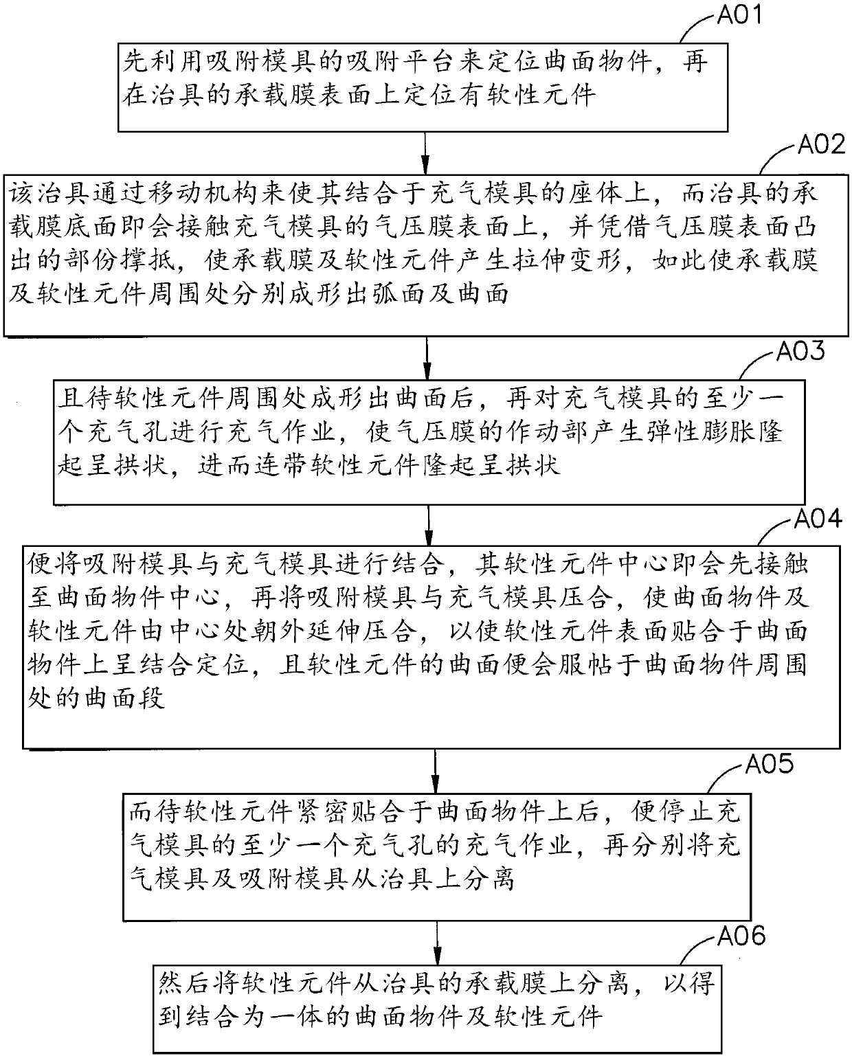
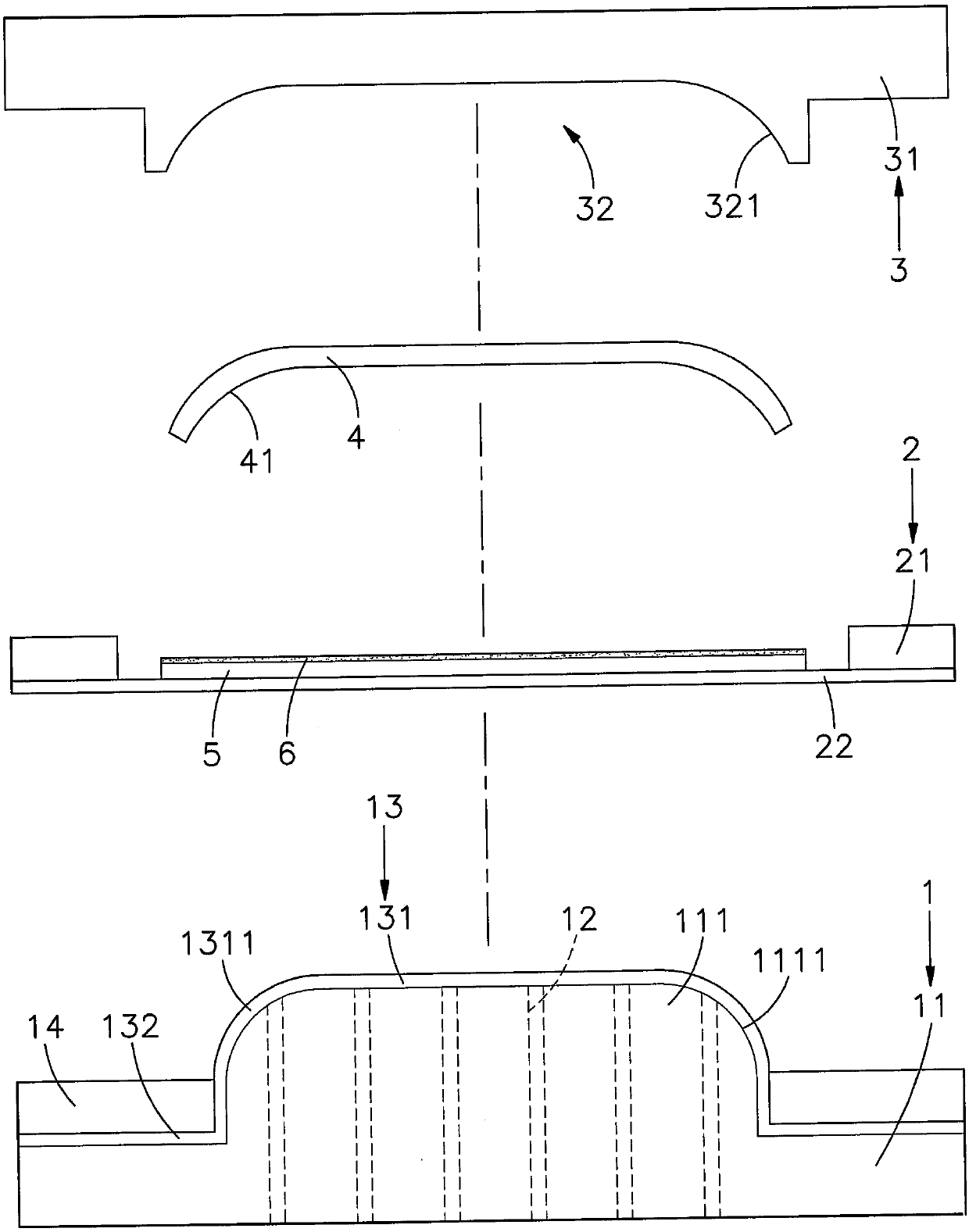
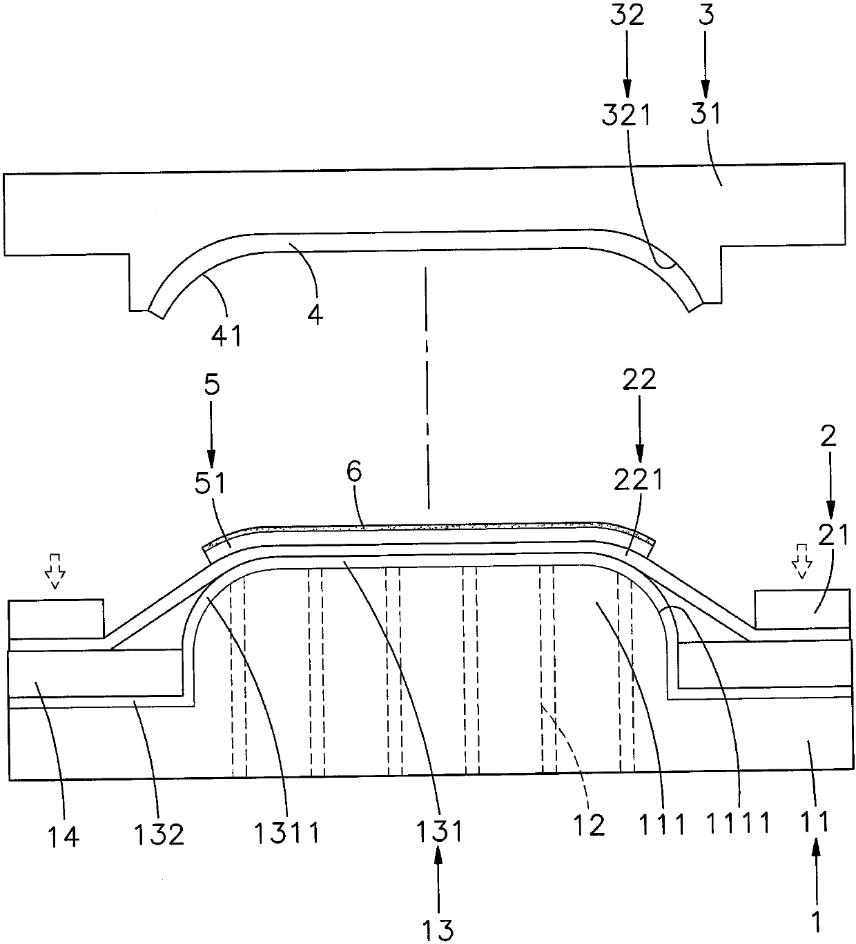
[0045] see figure 1 , figure 2 , image 3 , Figure 4 , Figure 5 , Figure 6 , Figure 7 Shown, be flow chart of the present invention, use status figure (one), (two), (three), (four), (five) and (six), can find out clearly from the figure, curved surface sticker of the present invention The combined device includes an inflatable mold 1, a jig 2 and an adsorption mold 3, wherein:

[0046] The inflatable mold 1 has a seat body 11, and a protruding block 111 is provided on the surface of the seat body 11, and an arc-shaped curved surface 1111 is formed around the top surface of the block block 111, and a connection to the...


PUM


Abstract

The invention provides a curved surface bonding apparatus and a bonding method thereof. An inflation mold can use at least one inflation hole to inflate an air pressure film to drive the central position of a soft component to be ridged to be arch-shaped, when the soft component and a curved surface object adsorbed by an adsorption mold are bonded to each other, the ridged center of the soft component can be used to really contact the center of the curved surface object, and then the outward extending and pressing is carried out from the center for close bonding and positioning to ensure thatgas between the curved surface object and the soft component is completely extruded outwards, so that no air bubbles are generated between the curved surface object and the soft component, and no optical refraction problem is caused due to the air bubbles. At the same time, the soft component can be prevented from generating wrinkles during the bonding process, and can be accurately and closely bonded to the curved surface object, so that the purpose of improving the producing process and the product qualification rate is achieved.

Description

technical field [0001] The invention relates to a curved surface laminating device and its laminating method, especially to use at least one air hole of the inflatable mold to inflate the air pressure film to drive the central bulge of the soft element, so that when the curved surface object is bonded to the soft element, It can be laminated from the center outward to ensure that the gas is completely discharged, so that there are no bubbles or wrinkles between the curved surface object and the soft component, thereby improving the overall qualification rate. Background technique [0002] By the way, today's manufacturing industry is facing serious problems of shortage of labor demand, processing operations that easily cause pollution to the environment, and the rising awareness of environmental protection, the increase in labor and operating costs, and the pressure of labor-intensive transformation into technology-intensive, Most of the industry responds to the rise in prod...

Claims


Application Information

Patent Timeline
IPC IPC(8): B32B37/00B32B37/10B32B37/12
CPCB32B37/003B32B37/0046B32B37/10B32B37/12
Inventor 黄秋逢叶君基黄国书林昶志
Owner USUN TECH CO LTD
Learn More