High-sulfur tail gas treatment system and technology

A tail gas treatment and high-sulfur technology, applied in the chemical industry, can solve the problems of low-temperature acid dew point corrosion of heat exchange equipment, low waste heat utilization rate, poor incineration effect, etc., to avoid low-temperature acid dew point corrosion, avoid acid dew point corrosion, Guarantee the effect of long-term stable operation

Pending Publication Date: 2019-07-26
LUOYANG RUICHANG PETROCHEM EQUIP
View PDF7 Cites 3 Cited by
  • Summary
  • Abstract
  • Description
  • Claims
  • Application Information

AI Technical Summary

Problems solved by technology

[0005] In view of this, the present invention aims to propose a high-sulfur tail gas treatment system and process to solve the poor incineration effect of the tail gas treatment unit of the Claus sulfur recovery unit in the prior art, and the H in the flue gas 2 S, NOx, and CO are not up to standard, high energy consumption, low utilization rate of waste heat, high concentration of SO in flue gas 2 For problems such as low-temperature acid dew point corrosion caused by heat exchange equipment

Method used


Image

  • High-sulfur tail gas treatment system and technology
  • High-sulfur tail gas treatment system and technology

Examples


Embodiment 1

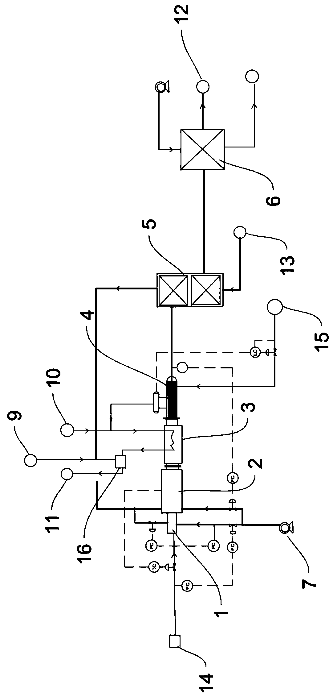
[0037] Such as figure 1 As shown, this embodiment provides a high-sulfur tail gas treatment system, including a tail gas incineration unit and a flue gas waste heat recovery unit. The tail gas incineration unit includes a burner 1 and an incinerator 2. The burner 1 and the incinerator 2 are connected through a flange or Welding type connection, the mixture of high-sulfur tail gas, fuel gas and combustion-supporting air passes through the incinerator 2 and then discharges high-temperature flue gas into the flue gas waste heat recovery unit. The flue gas waste heat recovery unit is set as multi-stage waste heat recovery equipment, including Pressurized steam superheater 3, steam generator 4, energy-saving heat exchange equipment 5, air preheater 6, combustion-supporting fan 7, etc. The fuel gas source 14 is connected to the burner, the fuel gas passes through the burner 1 and then enters the furnace for supplementary combustion, the steam superheater 3 is connected to the incine...

Embodiment 2

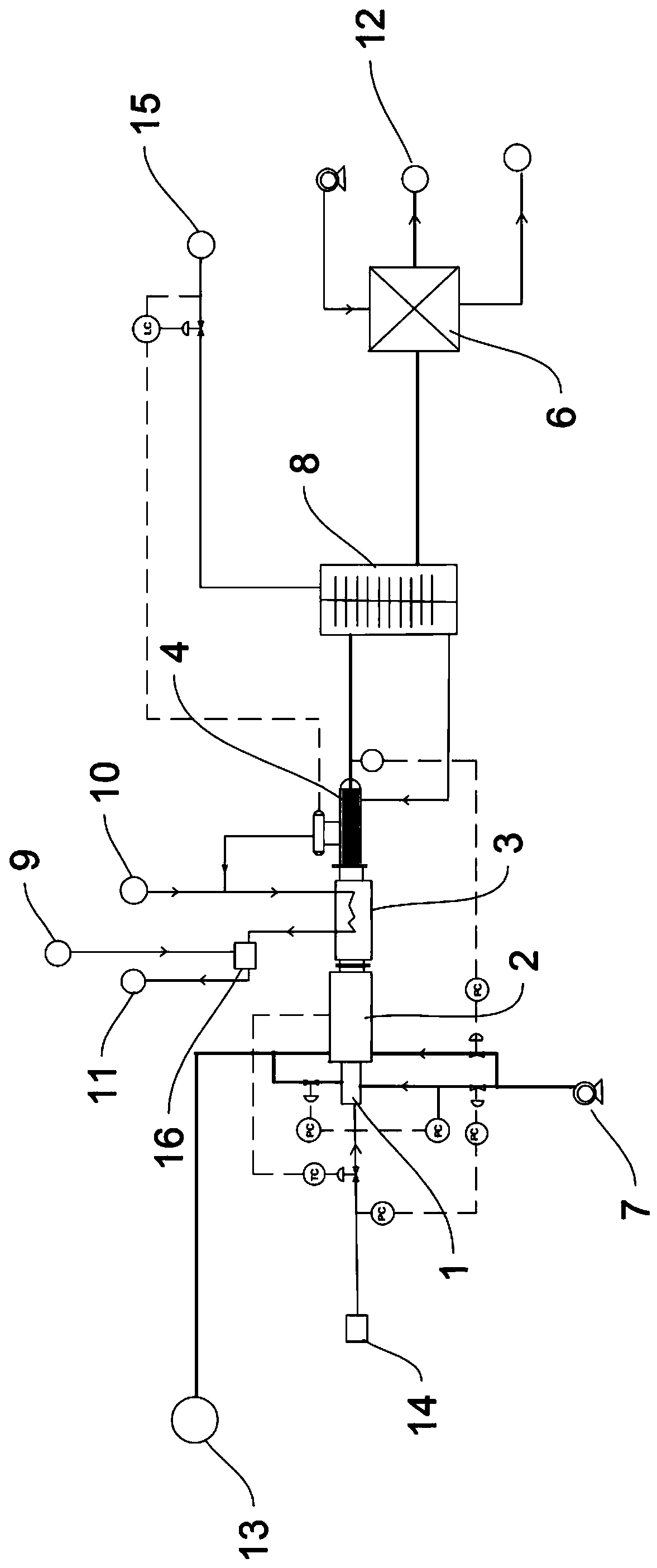
[0063] Such as figure 2 As shown, this embodiment provides a high-sulfur tail gas treatment system, including a tail gas incineration unit and a flue gas waste heat recovery unit. The tail gas incineration unit includes a burner 1 and an incinerator 2. The burner 1 and the incinerator 2 are connected through a flange or Welding type connection, the mixture of high-sulfur tail gas, fuel gas and combustion-supporting air passes through the incinerator 2 and then discharges high-temperature flue gas into the flue gas waste heat recovery unit. The flue gas waste heat recovery unit is set as multi-stage waste heat recovery equipment, including Pressurized steam superheater 3, steam generator 4, energy-saving heat exchange equipment, air preheater 6, combustion-supporting fan 7, etc. The fuel gas source 14 is connected to the burner, the fuel gas passes through the burner 1 and enters the furnace for combustion, the steam superheater 3 is connected to the incinerator 2, the steam g...


PUM


Abstract

The invention provides a high-sulfur tail gas treatment system and technology. The high-sulfur tail gas treatment system comprises a tail gas incineration unit and a flue gas waste heat recovery unit.The tail gas incineration unit comprises a combustor and an incinerator. The combustor and the incinerator are connected through a flange or in a welding mode. The mixed gas of high-sulfur tail gas,fuel gas and combustion air is burnt in the incinerator, and then high-temperature flue gas is discharged and enters the flue gas waste heat recovery unit. The flue gas waste heat recovery unit is setas multi-stage waste heat recovery facilities, and comprises a medium-pressure steam superheater, a steam generator, an energy-saving heat exchange facility and an air preheater. The steam superheater is connected with the incinerator, the steam generator is connected with the medium-pressure steam superheater, and the air preheater is connected with the tail end of the energy-saving heat exchange facility. According to the high-sulfur tail gas treatment system and technology, due to the design of multi-stage air distribution and tail gas flow separation of the incinerator, the emission indexrequirement can be met. Meanwhile, the equipment structure and materials of the waste heat recovery unit are optimized, and therefore the low-temperature acid dew point corrosion is avoided, and thelong-period stable operation is guaranteed.

Description

technical field [0001] The invention relates to the technical field of chemical industry, in particular to a high-sulfur tail gas treatment system and process. Background technique [0002] For a conventional Claus or Super Claus sulfur recovery unit, a tail gas incinerator is equipped at the end of the device to make the H contained in the tail gas 2 S, COS, S, etc. are completely incinerated to generate SO 2 , due to the low calorific value of the combustible components in the Claus tail gas, fuel gas needs to be added to the tail gas incinerator to maintain combustion, and the heat released during the combustion of fuel gas and air is used to make H 2 S, COS, S, etc. are converted into SO 2 , CO converted to CO 2 , the flue gas after incineration usually recovers part of the heat through the waste heat boiler and produces medium-pressure steam by-product. A large amount of waste heat is not fully utilized, resulting in waste of heat. [0003] In the existing Claus su...

Claims


Application Information

Patent Timeline
Patent Type & Authority Applications(China)
IPC IPC(8): F23G7/06F23G5/46F23J15/04F23J15/06F23L15/04F23L9/00F22B1/18
CPCF23G7/06F23G5/46F23J15/04F23J15/06F23L15/04F23L9/00F22B1/1892Y02E20/34
Inventor 刘颖孙东旭王丽洁马晓阳曹伟强
Owner LUOYANG RUICHANG PETROCHEM EQUIP
Why Eureka
Try Eureka