High efficiency broadband dual polarization cavity array antenna
An array antenna, dual-polarization technology, applied to antenna unit combinations with different polarization directions, antennas, antennas suitable for movable objects, etc. The effect of the need for polarized diversity
- Summary
- Abstract
- Description
- Claims
- Application Information
AI Technical Summary
Problems solved by technology
Method used
Image
Examples
specific Embodiment approach
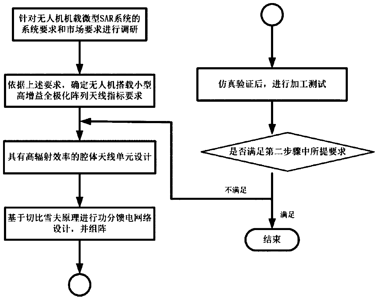
[0023] The preferred embodiment of the high-efficiency broadband dual-polarization cavity array antenna of the present invention is:
[0024] include:
[0025] Rectangular opening waveguide antenna is used as the array unit form, fed by strip line, and double-polarized feed is realized by the laminated structure of multi-layer PCB substrate, at the same time, the unit structure is formed by using the strip line to form a sub-feed network Expand to 16×4 antenna array;
[0026] Carrying out weighting processing based on the Chebyshev principle on the power distribution feed network to suppress the antenna side lobe level;
[0027] The antenna array is fed by SMA connectors to improve the portability of the antenna, and the conversion from stripline to coaxial line is designed at the end of the feeding network, and when the stripline is buried in the multilayer PCB In the substrate, the broadband conversion structure from the stripline to the coaxial line is still designed, and...
specific Embodiment
[0066] By weighing the requirements of miniaturization and high gain, we designed a 16*4 antenna array. In order to meet the requirements of the antenna array for low sidelobe, Chebyshev weighting is performed on the entire antenna feed line. Since the 1dB gain bandwidth of the antenna is relatively wide, the series feed grid should not be used here, but the parallel feed network should be used. The overall structure of the antenna is as Figure 2-8 shown. The antenna has 7 layers of dielectric boards, and the dielectric boards are bonded with PP sheet FR-28. The schematic diagram of the layered structure is as follows: Figure 7 shown. The electromagnetic full-wave simulation software HFSS is used to simulate and optimize the antenna structure, which is mainly marked as VSWR and sidelobe level. The reason why the antenna gain is not optimized is that the antenna gain is almost entirely determined by the sidelobe balance and VSWR when the feed loss and antenna aperture are...
PUM
 Abstract
Description
Claims
Application Information
 - R&D
- Intellectual Property
- Life Sciences
- Materials
- Tech Scout
- Unparalleled Data Quality
- Higher Quality Content
- 60% Fewer Hallucinations
Browse by: Latest US Patents, China's latest patents, Technical Efficacy Thesaurus, Application Domain, Technology Topic, Popular Technical Reports.
© 2025 PatSnap. All rights reserved.Legal|Privacy policy|Modern Slavery Act Transparency Statement|Sitemap|About US| Contact US: help@patsnap.com


