A new type of waste heat recycling system and method at cold end of power plant

A cold end and waste heat technology of a power plant, applied in steam application, machine operation mode, machines using waste heat, etc., can solve the problems of low waste heat utilization rate, environmental pollution, energy waste, etc., and achieve high waste heat utilization rate and environmental protection Effects of pollution and saving investment

Active Publication Date: 2021-08-27
孔泽学
View PDF5 Cites 0 Cited by
  • Summary
  • Abstract
  • Description
  • Claims
  • Application Information

AI Technical Summary

Problems solved by technology

[0003] The invention overcomes the low utilization rate of waste heat generated in the power generation process in the prior art, which is easy to cause energy waste and environmental pollution, and provides a new type of waste heat recycling system and method at the cold end of the power plant, which has a high waste heat utilization rate, Not easy to cause energy waste and environmental pollution

Method used


Image

  • A new type of waste heat recycling system and method at cold end of power plant
  • A new type of waste heat recycling system and method at cold end of power plant
  • A new type of waste heat recycling system and method at cold end of power plant

Examples


Embodiment

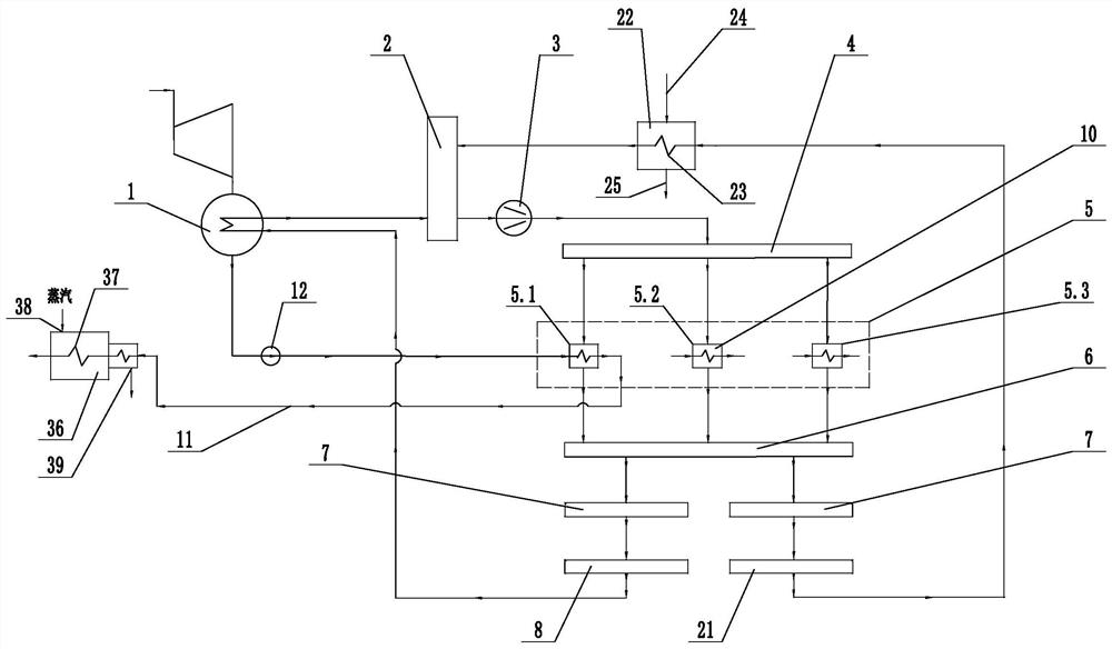
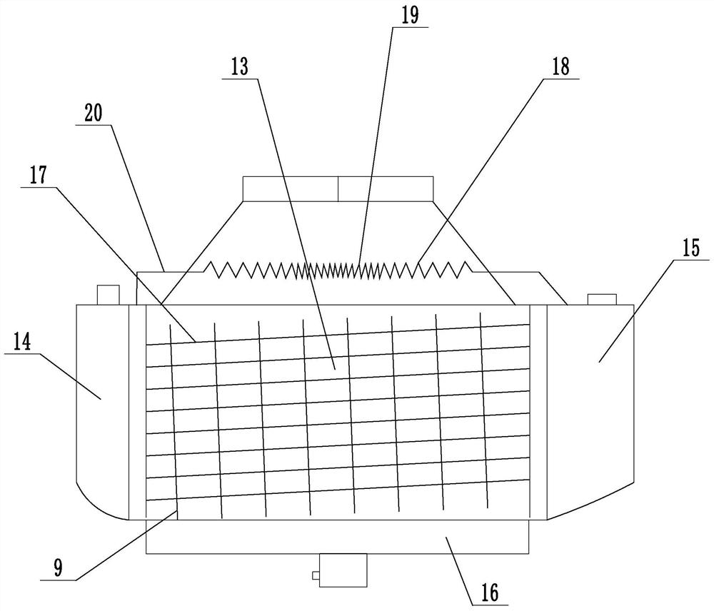
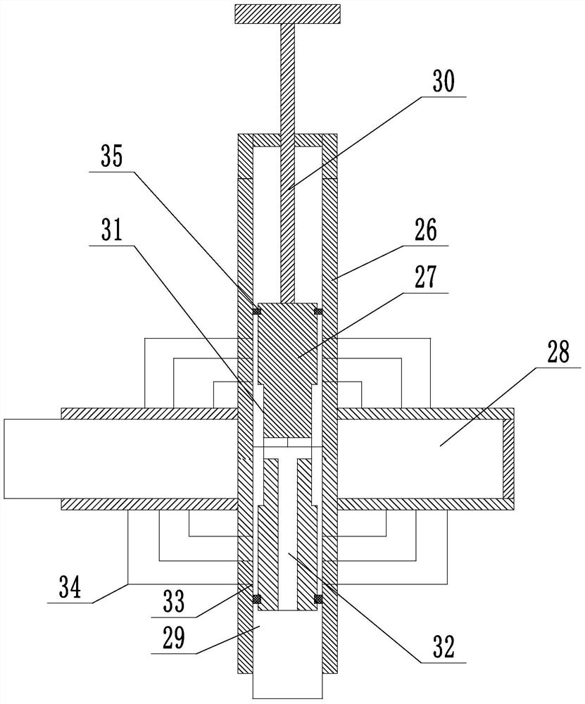
[0019] Example: A new type of waste heat recycling system at the cold end of a power plant (see attached figure 1 to attach image 3 ), including the main evaporator condenser 1, the gaseous refrigerant receiving header 2 after absorbing heat and evaporation, the refrigeration compressor unit 3, the compressed high-temperature and high-pressure gaseous refrigerant receiving header 4, several heat exchangers 5, and the liquid refrigerant receiving header Box 6, liquid refrigerant throttling valve group 7, mainstream refrigerant pressure stabilizing header 8; refrigerant evaporation tube 9 is installed in the main evaporation condenser, and one end of the refrigerant evaporation tube is connected to the gaseous refrigerant receiving header after heat absorption and evaporation The other end is connected with the mainstream refrigerant pressure stabilizing header. There is a refrigerant condensation chamber 10 in the heat exchanger. The refrigerant condensation chamber is connect...


PUM


Abstract

The invention discloses a novel system and method for recycling residual heat at the cold end of a power plant, aiming at solving the problems in the prior art that the utilization rate of the residual heat generated in the power generation process is low, easily causing energy waste and environmental pollution. The invention includes a main evaporation condenser, a gaseous refrigerant receiving header after heat absorption and evaporation, a refrigeration compressor unit, a compressed high-temperature and high-pressure gaseous refrigerant receiving header, several heat exchangers, a liquid refrigerant receiving header, and a liquid refrigerant receiving header. Throttle valve group, mainstream refrigerant pressure stabilizing header; refrigerant evaporating tube is installed in the main evaporating condenser, one end of the refrigerant evaporating tube is connected with the gaseous refrigerant receiving header after heat absorption and evaporation, and the other end is connected with the mainstream refrigerant stabilizing The pressure header is connected; the refrigerant condensing pipe is installed in the heat exchanger, and the refrigerant condensing pipe is connected between the compressed high-temperature and high-pressure gaseous refrigerant receiving header and the liquid refrigerant receiving header, and the inlet of the heat exchanger is connected to the low-temperature return pipe The outlet of the heat exchanger is connected to the pipe network of high-temperature water users.

Description

technical field [0001] The invention relates to a waste heat utilization technology, more specifically, it relates to a novel system and method for recycling waste heat at the cold end of a power plant. Background technique [0002] The traditional cold end cycle system of a power plant is one pole of the thermodynamic cycle system for steam turbine power generation; its main function is to condense the exhausted steam that has done work through a surface condenser (water-cooled or air-cooled) to condense and release heat into water, and through the main The condensed water is pumped into the circulation loop and then heated. The second is to take out the huge condensation heat of the exhausted steam, because only by taking out the condensation heat can it condense into water, complete the previous cycle, and start the cycle again. The traditional cold end systems include DC water supply cooling system, wet cooling tower cooling system, dry air cooling system and indirect ai...

Claims


Application Information

Patent Timeline
Patent Type & Authority Patents(China)
IPC IPC(8): F01K17/02F25B27/02
CPCF01K17/02F25B27/02Y02A30/274
Inventor 孔泽学
Owner 孔泽学
Why Eureka
Try Eureka