A multi-pole and multi-electron injection radiation source based on cold cathode

A technology of multi-electron beams and radiation sources, which is applied in the field of vertical multi-pole multi-electron beam radiation sources, can solve the problems of limited energy absorbed by modulated electron beams, fast electron beam speed, difficulties in manufacturing and assembly, etc. Improvement of interaction efficiency, injection wave interaction efficiency, and reduction of emission voltage requirements

Active Publication Date: 2020-09-25
UNIV OF ELECTRONICS SCI & TECH OF CHINA
View PDF6 Cites 0 Cited by
  • Summary
  • Abstract
  • Description
  • Claims
  • Application Information

AI Technical Summary

Problems solved by technology

[0004] With the development of microwave electric vacuum devices towards the terahertz frequency band, the size of the devices must become smaller and smaller due to the higher frequency and smaller wavelength; on the one hand, it will bring difficulties in manufacturing and assembly, on the other hand, it will also make electronic The space and time for the interaction between the beam and the high-frequency field are getting smaller and smaller, which makes the speed and density modulation of the electron beam insufficient, and the output power of the device is limited.
In order to develop an integrated vacuum microelectronic radiation source, the influence of beam-wave interaction has become a key technical difficulty. Vacuum microelectronic devices are usually small in size and the electron beam speed is relatively fast. The limited interaction time makes the modulation of electron beam from high The energy absorbed by the frequency field is limited

Method used


Image

  • A multi-pole and multi-electron injection radiation source based on cold cathode
  • A multi-pole and multi-electron injection radiation source based on cold cathode
  • A multi-pole and multi-electron injection radiation source based on cold cathode

Examples


Embodiment Construction

[0028] The present invention will be described in further detail below in conjunction with the accompanying drawings and embodiments.

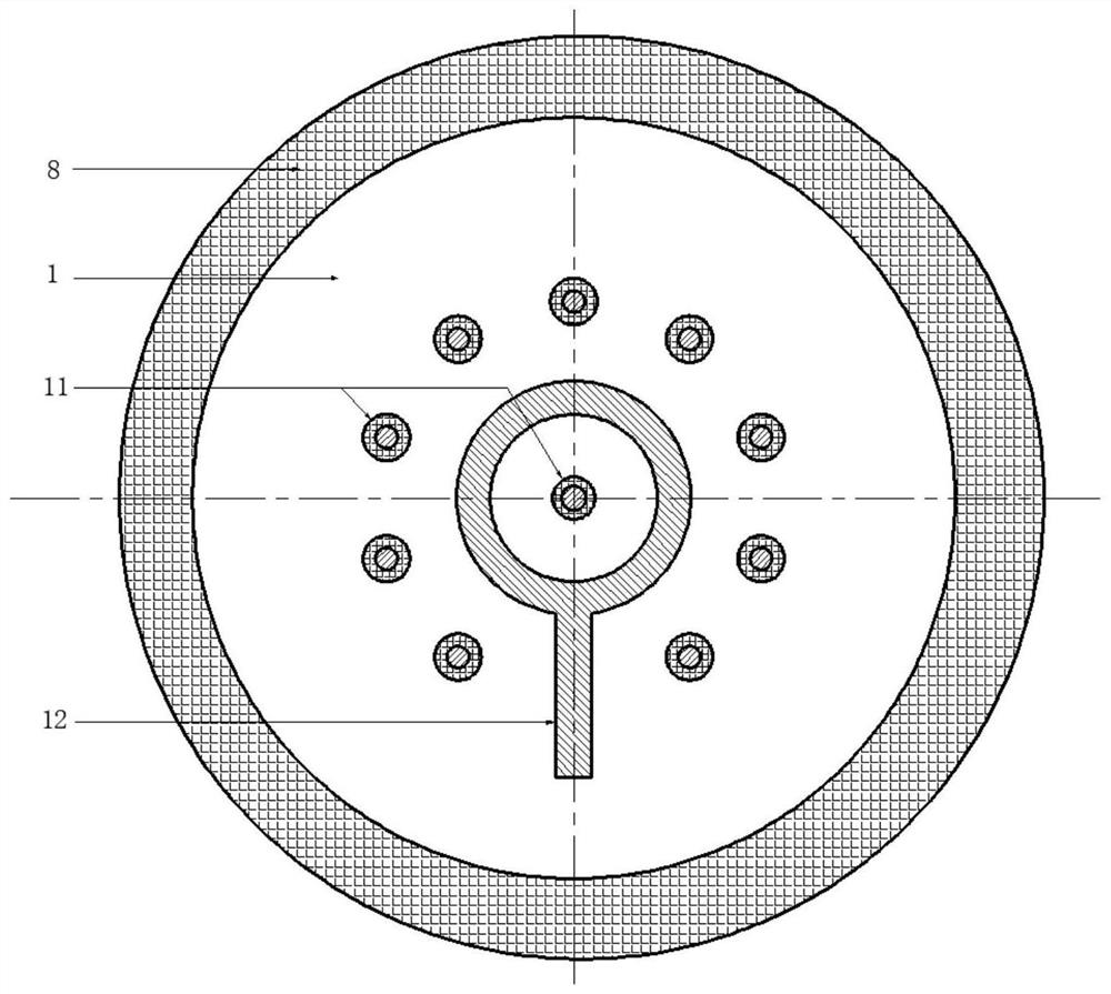
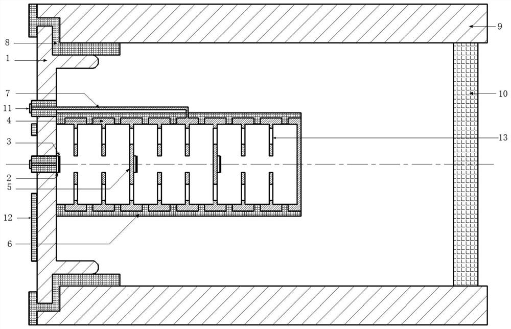
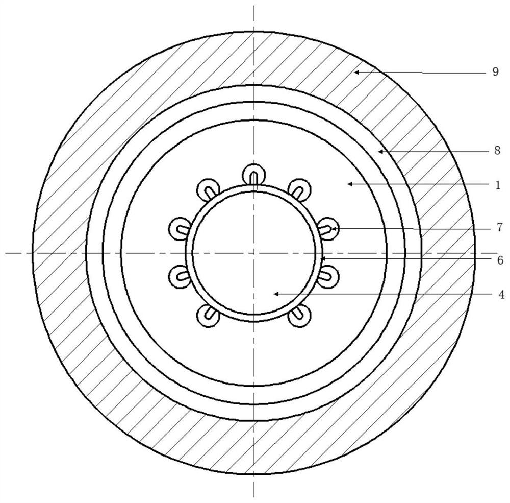
[0029] This embodiment provides a multi-pole and multi-electron injection radiation source based on cold cathode, its structure is as follows Figure 1 ~ Figure 4 shown; specifically include: cathode baffle, radiation source core, feed system, metal casing and output window; where,

[0030] The material of the cathode baffle 1 is metal, the center is connected to the radiation source core, and the periphery is connected to one end of the metal shell 9 through an insulator 8, and the output window is packaged at the other end of the metal shell 9;

[0031] The feed system includes a metal wire 7, an electrode 12 and an insulating medium. There are several small holes on the cathode baffle, and one end of the metal wire passes through the small hole to connect the radiation source core and the other end to the electrode. The metal wire and the c...


PUM

PropertyMeasurementUnit
diameteraaaaaaaaaa
thicknessaaaaaaaaaa
diameteraaaaaaaaaa

Abstract

The invention belongs to the field of microwave, millimeter wave and terahertz frequency band electric vacuum devices, and specifically provides a cold cathode-based multi-pole and multi-electron injection radiation source. The invention mainly includes a cathode baffle, a radiation source core, a power feeding system, a metal casing and an output window; through multi-level emission and multi-pole modulation, the strong high-frequency field in the middle of the high-frequency structure is fully utilized to act on the cold cathode surface, thereby increasing the emission current and deepening the electron beam modulation depth, so that the electron beam has a significant pre-modulation effect. The invention can obtain a very high-quality field emission pre-modulated electron beam, the beam-wave interaction efficiency has been significantly improved, and the output power has been significantly increased; the advantage of not requiring an electron optical system greatly reduces the complexity of the device, and through fine Processing, the size of the device can reach the order of microns, and the integration and miniaturization of millimeter wave, submillimeter wave, and terahertz radiation sources can be realized.

Description

technical field [0001] The invention belongs to the field of microwave, millimeter wave and terahertz frequency band electric vacuum devices, in particular to a cold cathode-based vertical multi-pole multi-electron injection radiation source. Background technique [0002] Vacuum electron radiation sources are widely used in radar, communication and particle acceleration systems because of their high power and high frequency. The electron gun in the traditional electric vacuum radiation source device generally adopts the thermal emission cathode system. After decades of development, the thermal emission cathode process has been very mature; however, due to the high operating voltage and high operating temperature of the thermal cathode, the device is easy to The damage and long start-up time limit their application to vacuum electron radiation sources. The rapid development of solid-state radiation source devices has challenged vacuum devices in many fields. Their small size...

Claims


Application Information

Patent Timeline
Patent Type & Authority Patents(China)
IPC IPC(8): H01J19/24H01J19/57H01J19/60
CPCH01J19/24H01J19/57H01J19/60
Inventor 袁学松王瑞陈青云鄢扬王彬李海龙殷勇蒙林
Owner UNIV OF ELECTRONICS SCI & TECH OF CHINA
Why Eureka
Try Eureka