Planar optical device capable of generating vertex light fields in double channels of near field and far field simultaneously and design and preparation of planar optical device

A technology of optical devices and vortex light, applied in optical components, optics, instruments, etc., to achieve the effect of broad application prospects

Active Publication Date: 2019-09-27
PEKING UNIV
View PDF4 Cites 9 Cited by
  • Summary
  • Abstract
  • Description
  • Claims
  • Application Information

AI Technical Summary

Problems solved by technology

However, the current planar vortex generation devices based on metasurface materials can only generate vortex light fields in the near-field or far-field channels respectively, and realize a vortex light field that can simultaneously generate vortex light fields

Method used


Image

  • Planar optical device capable of generating vertex light fields in double channels of near field and far field simultaneously and design and preparation of planar optical device
  • Planar optical device capable of generating vertex light fields in double channels of near field and far field simultaneously and design and preparation of planar optical device
  • Planar optical device capable of generating vertex light fields in double channels of near field and far field simultaneously and design and preparation of planar optical device

Examples


preparation example Construction

[0090] The preparation method of the planar optical device for simultaneously generating a vortex light field in the near-field and far-field dual channels based on the Ti / Au metal thin film and the rectangular nanohole array is further given below, and its preparation includes the following steps:

[0091] Step 1. Obtain SiO 2 (Quartz glass) transparent substrate, use an organic solvent and an ultrasonic cleaning machine to clean the substrate, and perform ultrasonic cleaning in the order of acetone (10-15min) → ethanol (10-15min) → deionized water (10-15min), Finally, dry the deionized water remaining on the substrate with a nitrogen gun to obtain clean SiO 2 transparent substrate;

[0092] Step 2, coat the metal film layer on the cleaned transparent substrate, and use the method of electron beam evaporation to coat the SiO obtained in the previous step 2 5nm-10nm Ti and 100nm-120nm Au are sequentially plated on the transparent substrate to obtain a substrate coated with a...

Embodiment 1

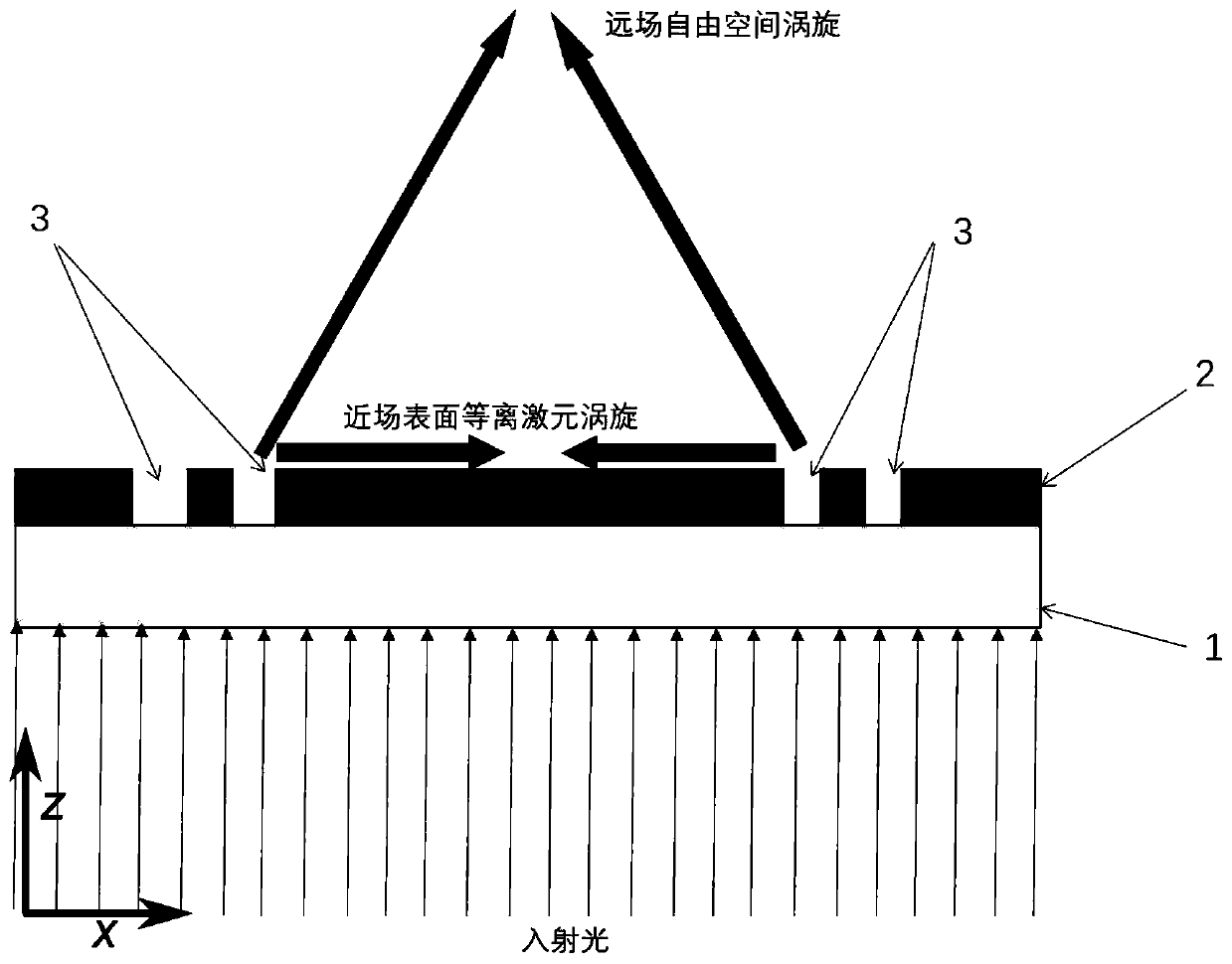
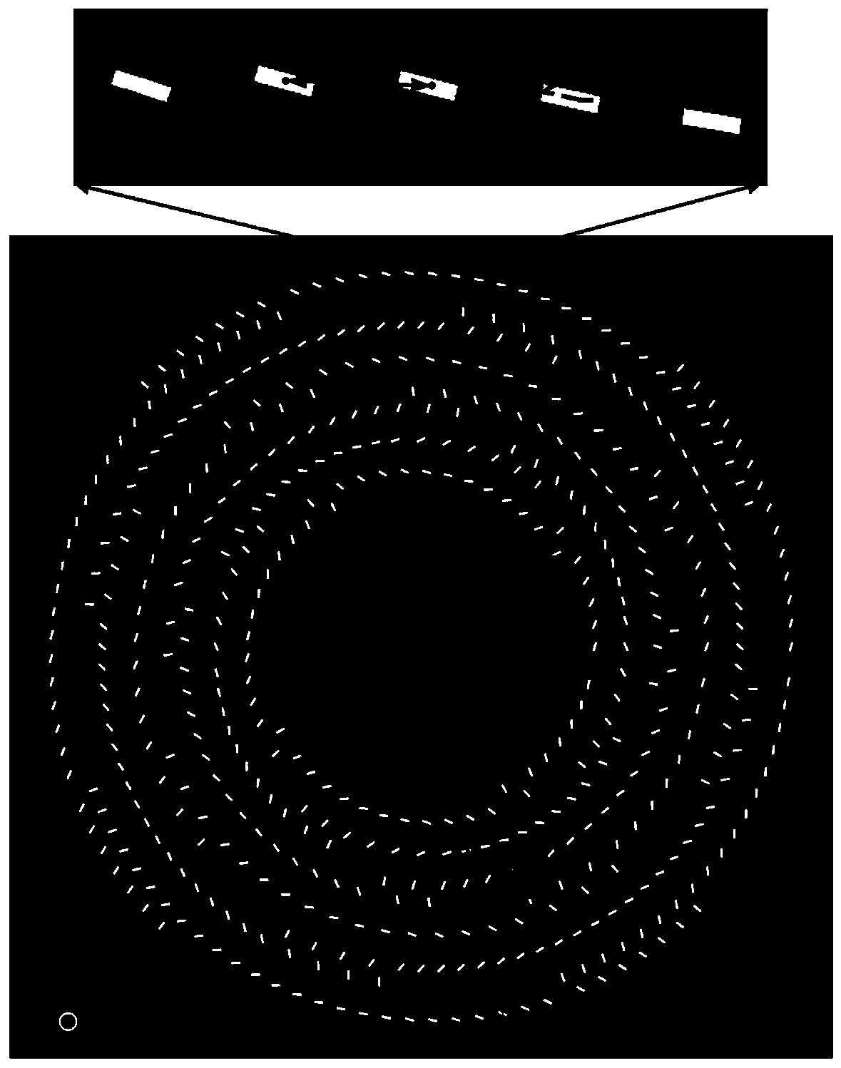
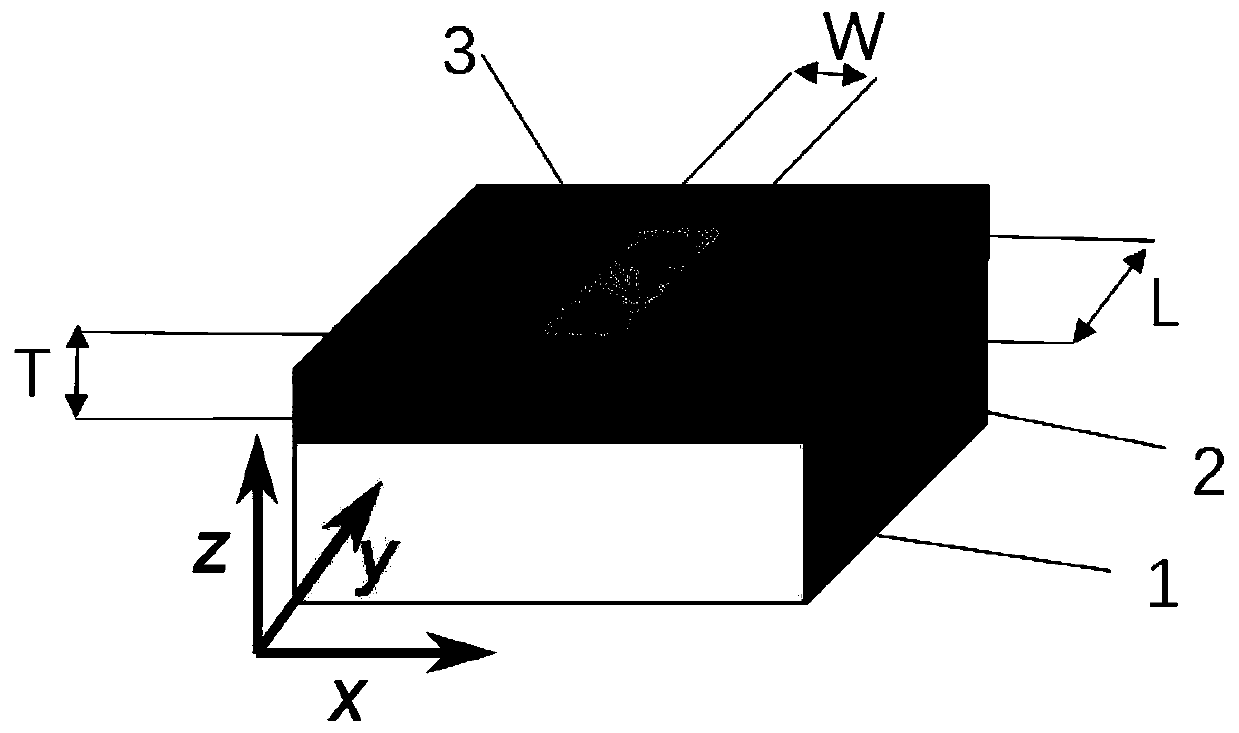
[0098] Scanning electron microscope (SEM) images of a planar optical device based on Ti / Au metal thin films and rectangular nanohole arrays for dual-channel generation of vortex light fields in the near-field and far-field simultaneously. Figure 6 As shown, its structure and principle are as Figure 1-3 shown, which includes SiO 2 There are three parts: a transparent substrate 1 , a Ti / Au metal thin film 2 and a rectangular nanohole array (metasurface structure) 3 . Of which SiO 2 The transparent substrate 1 is at the bottom, and the Ti / Au metal film 2 is located on the SiO 2 On the transparent substrate 1, a rectangular nanohole array (metasurface structure) 3 is processed in a Ti / Au metal thin film 2 by focused ion beam etching (FIB). The total thickness of the Ti / Au metal film 2 is 105nm, wherein the thickness of Ti is 5nm, and the thickness of Au is 100nm. 2 on a transparent substrate 1. Such as figure 2 As shown, the rectangular nanohole array pattern is circular,...


PUM

PropertyMeasurementUnit
Thicknessaaaaaaaaaa
Thicknessaaaaaaaaaa
Radiusaaaaaaaaaa

Abstract

The invention discloses a planar optical device capable of generating vertex light fields in doubles channels of a near field and a far field simultaneously and a design method and a preparation method of the planar optical device. According to the planar optical device, simultaneous generation of the vertex light fields in the two channels of the near field and the far field is realized for the first time by use of a metallic super-structure surface material, wherein a focused surface plasmon vertex light field exists in the near field, a focused free space vertex light field exists in the far field, and topological loads carried in the vertex light fields generated in the two channels can be flexibly matched according to demands. The planar optical device which is designed by use of the method and can generate the double-channel vertex light fields has an important meaning for a high-density communication and multifunctional integrated optical system based on the vertex light fields in the future.

Description

technical field [0001] The invention relates to a planar optical device, in particular to a light field manipulation device based on a metal surface plasmon metasurface material and a design method thereof, which can be used to design a The channel is a planar optical device for generating a vortex light field, and any configuration of the topological charge of the vortex light field generated by the two channels can be realized as required. Background technique [0002] The vortex light field is a special light field mode in which the wavefront has the characteristics of a spiral phase distribution. Compared with the ordinary light field, because its wavefront is a spiral phase distribution, a phase singularity will be generated in the center of the beam, and the light intensity at this singularity is zero, so that the cross section of the vortex beam shows a doughnut-shaped circle Ring light intensity distribution. On the other hand, compared to ordinary circularly polar...

Claims


Application Information

Patent Timeline
IPC IPC(8): G02B5/00G02B27/00
CPCG02B5/008G02B27/0012
Inventor 方哲宇蒋瞧朱星
Owner PEKING UNIV
Why Eureka
Try Eureka