Check patentability & draft patents in minutes with Patsnap Eureka AI!

Single crystal laser optical fiber based on surface microstructures as well as production method and application thereof

A microstructure and optical fiber technology, applied in microstructure optical fibers, glass optical fibers, clad optical fibers, etc., can solve the problems of reducing the transmission efficiency and service life of optical fibers, complicated preparation process routes, and thermal effects of optical fibers, so as to reduce the optical waveguide modulus. , avoid the complex process, the effect of high preparation efficiency

Active Publication Date: 2019-10-11
SHANDONG UNIV
View PDF15 Cites 6 Cited by
  • Summary
  • Abstract
  • Description
  • Claims
  • Application Information

AI Technical Summary

Problems solved by technology

[0006] In view of the shortcomings of the existing technology, especially the traditional heterogeneous cladding not only has the problems of complex preparation process, poor repeatability and high loss; but also serious thermal effects will occur inside the optical fiber, thereby reducing the transmission efficiency and service life of the optical fiber

Method used


Image

  • Single crystal laser optical fiber based on surface microstructures as well as production method and application thereof
  • Single crystal laser optical fiber based on surface microstructures as well as production method and application thereof
  • Single crystal laser optical fiber based on surface microstructures as well as production method and application thereof

Examples


Embodiment 1

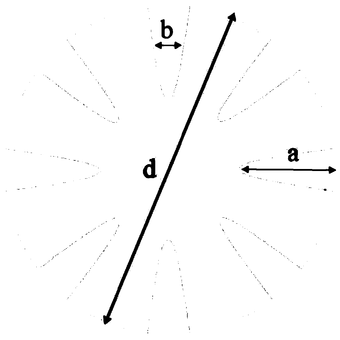
[0042] Such as figure 1 As shown, a femtosecond laser is used to perform microstructure processing on a sapphire single crystal fiber with a diameter of d=10μm and a length of 10cm, that is, a groove is uniformly cut on the surface of the single crystal fiber, and the shape of the groove end is parabolic. The depth a=1μm, the width of the paraboloid's midline is b=0.2μm; the groove spacing is equal, and the number of grooves processing around the core is 8.

Embodiment 2

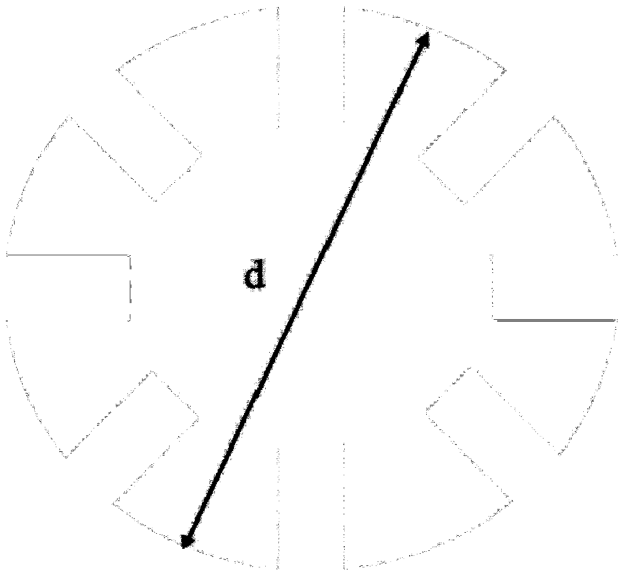
[0044] Such as figure 2 As shown, a femtosecond laser is used to perform microstructure processing on a sapphire single crystal fiber with a diameter of d=10μm and a length of 10cm. That is, grooves are uniformly cut on the surface of the single crystal fiber, and the shape of the groove end is rectangular, and the groove depth a=1μm, groove width b=0.2μm; groove spacing is equal, and the number of grooves processed around the core is 8.

Embodiment 3

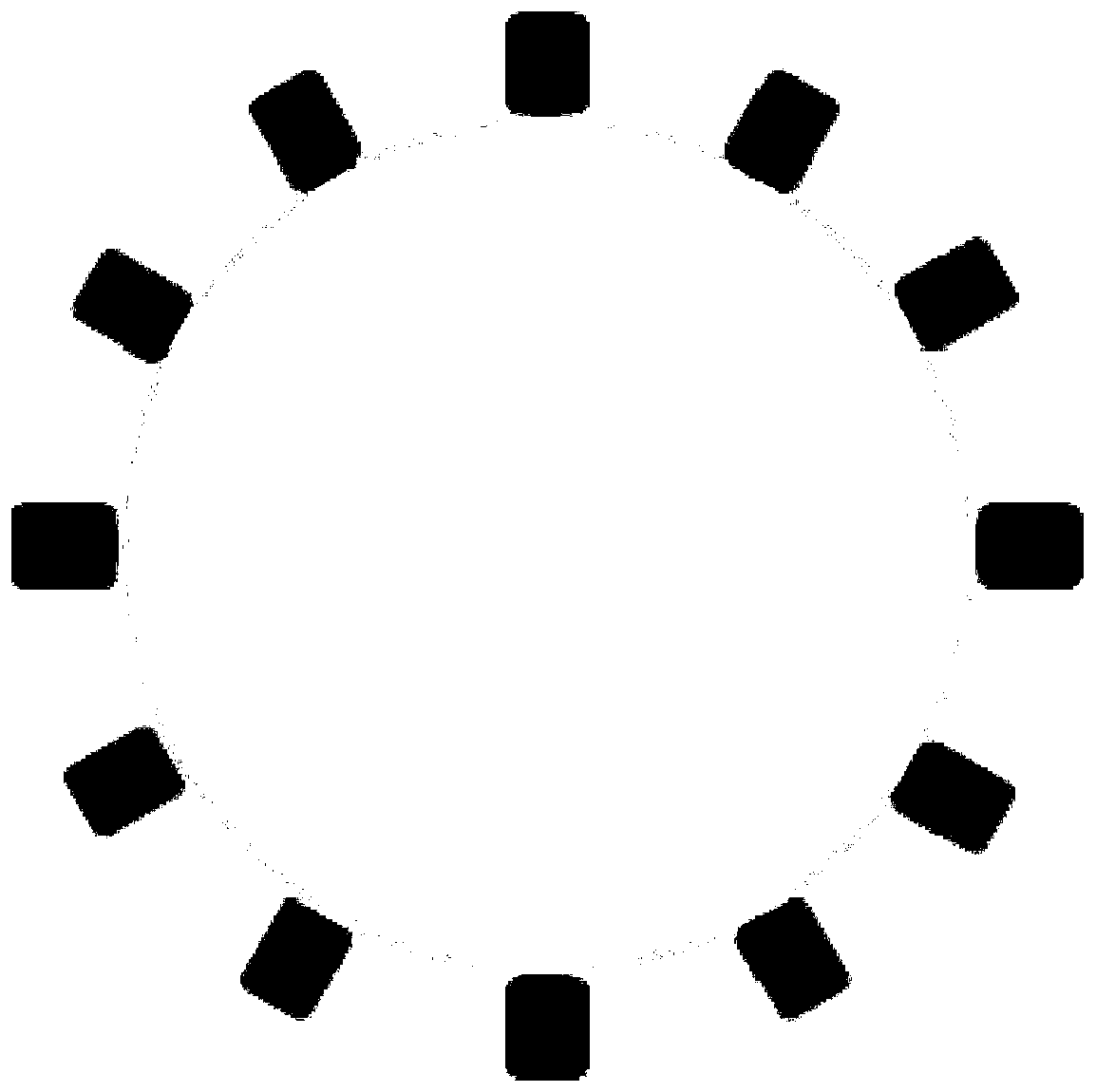
[0046] As described in Example 2, the difference is that the groove processing width b=0.4 μm.


PUM

PropertyMeasurementUnit
Groove depthaaaaaaaaaa
Groove widthaaaaaaaaaa
Depthaaaaaaaaaa

Abstract

The invention relates to a single crystal laser optical fiber based on surface microstructures as well as a production method and an application thereof. By designing and processing micro-nano structures on the surface of a single crystal optical fiber, the size of a fiber core can be effectively reduced, mode number of an optical waveguide is greatly reduced, an effective constraint on a transmitted light beam is realized, and the traditional process route of a glass optical fiber is completely replaced. The structures can be formed by processing by virtue of material modification methods such as femtosecond laser, ion implantation and chemical corrosion, the microstructures in different shapes respectively can realize high-efficiency optical waveguide performance, and the mode number ofthe optical waveguide can be effectively adjusted by changing processing depths and processing line widths of the microstructures. The single crystal laser optical fiber provided by the invention canavoid energy loss caused by coating of a cladding, preparation efficiency is higher, repeatability is better, and controllability is better. Therefore, the single crystal laser optical fiber providedby the invention has an important application prospect in optical waveguide mode number control and single mode optical waveguides and in the fields of remote information communication and high-energylasers.

Description

Technical field [0001] The invention relates to a novel full-single crystal laser fiber with a surface microstructure cladding, which belongs to the field of new materials and laser technology. Background technique [0002] Single crystal fiber is a new type of one-dimensional functional crystal material. It has the characteristics of high aspect ratio and large specific surface area of ​​glass fiber, and has the advantages of good heat dissipation, high efficiency, and simple thermal management; the material itself is derived from the excellent performance of the single crystal fiber. Crystal material has the advantages of high thermal conductivity, good infrared permeability, high damage threshold, and low nonlinear effects. Therefore, single crystal fiber has great application prospects in the field of high-power fiber lasers, especially in the field of infrared fiber lasers, and will have significant application value in the fields of military, information communication, mate...

Claims


Application Information

Patent Timeline
IPC IPC(8): G02B6/02
CPCG02B6/02295G02B6/02395
Inventor 贾志泰王涛陶绪堂张健
Owner SHANDONG UNIV
Features
  • R&D
  • Intellectual Property
  • Life Sciences
  • Materials
  • Tech Scout
  • Unparalleled Data Quality
  • Higher Quality Content
  • 60% Fewer Hallucinations
Learn More