Electrified railway through-type traction power supply system

A traction power supply system, electrified railway technology, applied in electric braking system, electrical components, railway transportation, etc., can solve the problem of active power and reactive power traction network voltage fluctuation, instrument measurement accuracy and normal communication impact, natural resources difficult Fully utilized and other issues, to achieve the effect of strong substitutability, easy safety redundancy design, and easy system maintenance

Pending Publication Date: 2019-10-18
SOUTHWEST JIAOTONG UNIV
View PDF0 Cites 16 Cited by
  • Summary
  • Abstract
  • Description
  • Claims
  • Application Information

AI Technical Summary

Problems solved by technology

Harmonic current may cause harmonic resonance in the traction power supply system, threaten the safety of electrical equipment, and also affect the measurement accuracy of instruments and normal communication
[0003] In order to solve the above-mentioned traction power supply problem, some scholars have proposed a common-phase power supply technology, but this technology can only cancel the phase separation of the electricity in the station, and the electricity separation between the stations still exists.
In order to completely solve the problem of power quality and excessive equalization, scholars from Southwest Jiaotong University proposed a feed-through traction power supply system consisting of a front-end step-down transformer, a three-phase-single-phase converter and an output step-up transformer. The structure requires a large-capacity filter device and a step-up transformer to be connected to the output of the converter. In addition, there are many problems that need to be solved urgently, such as excessive current in the intermediate link, poor expandability of the converter, and limited output voltage control accuracy.
[0004] In addition, the natural resources along the railway line are abundant, and new energy sources such as

Method used


Image

  • Electrified railway through-type traction power supply system
  • Electrified railway through-type traction power supply system
  • Electrified railway through-type traction power supply system

Examples


Example Embodiment

[0025] The present invention will be further described in detail below with reference to the accompanying drawings and specific embodiments.
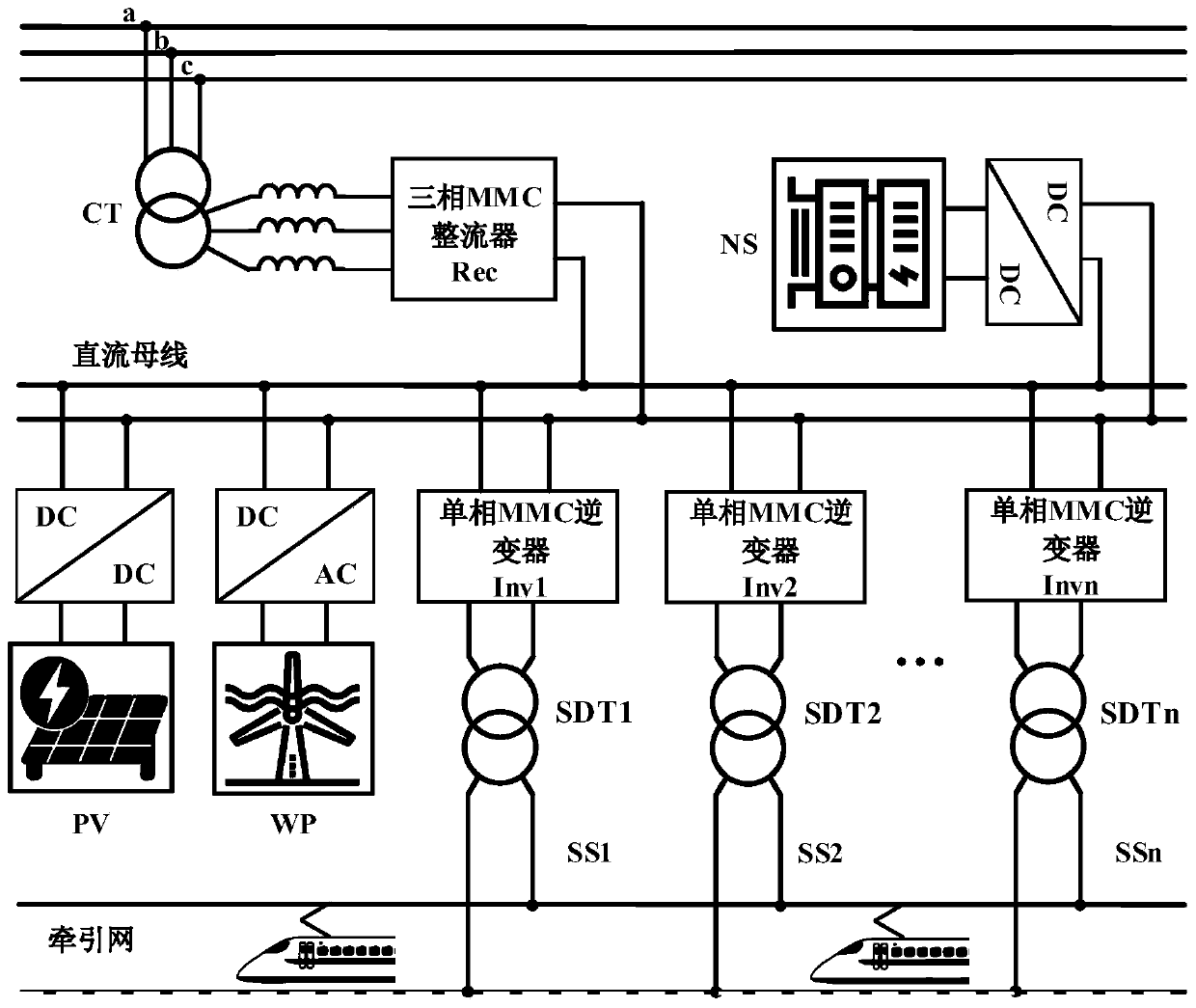
[0026] figure 1 A feed-through traction power supply system for electrified railways proposed by the present invention includes connecting transformer CT, three-phase MMC rectifier Rec, DC bus, single-phase MMC inverter Inv of traction substation, single-phase step-down transformer SDT, railway traction network. The three-phase MMC rectifier Rec is connected to the a, b, and c phases of the three-phase public power grid through the connection transformer CT, and the output DC side is connected to the DC bus, which is connected to the traction substations SS1, SS2, ..., SSn along the railway line. The single-phase MMC inverter Inv is connected to the input end, and its output single-phase alternating current is connected to the primary winding of the step-down transformer SDT. The secondary side of the step-down transformer SDT outputs ...


PUM


Abstract

The invention provides an electrified railway through-type traction power supply system, and belongs to the technical field of railway traction power supply systems. The traction power supply system is characterized in that the output end of a connection transformer CT is connected with an alternating current side of a three-phase MMC rectifier through a filter inductance Ls, and a direct currentside DC is connected with a direct current bus; the input end of a single-phase MMC inverter is connected with the direct current bus, the output side is connected with a single-phase step-down transformer SDT primary winding, and single-phase alternating current, with output voltage of 27.5 kV, of the secondary side of the single-phase step-down transformer is connected into a railway traction network to supply power to trains. The alternating current side of a AC-DC transformer of wind power generation WP is connected with the output of a fan, the direct current output side is connected thedirect current bus, one side of a DC-DC converter of photovoltaic power generation PV is connected with the output of a photovoltaic panel, the other side of the DC-DC converter of the photovoltaic power generation PV is connected with the direct current bus; and one side of a DC-DC converter of an energy storage system NS is connected with a hybrid energy storage system formed by a storage battery and a super capacitor, and the other side of the DC-DC converter of the energy storage system NS is connected with the direct current bus.

Description

technical field [0001] The invention belongs to the technical field of railway traction power supply system. Background technique [0002] At present, three-phase-two-phase step-down transformers are mostly used in my country's railway system to supply power to the traction network. However, due to the different power grids taken by different traction substations and the traction transformers, it is difficult to achieve the phase, amplitude and frequency of the two-phase output voltage. They are exactly the same, so electric phase splitting needs to be set between different traction substations and between two-phase outputs of the same traction substation. Due to the existence of electric phase separation, there is a power supply dead zone in the traction network, and the train can only slide by inertia, which seriously restricts the running speed of the train and threatens the safety of the train operation. Moreover, due to the existence of electric split phases, the capaci...

Claims


Application Information

Patent Timeline
IPC IPC(8): B61C3/00B60L7/10H02J3/38H02J3/32H02M7/5387
CPCH02J3/383B61C3/00B60L7/10H02J3/32H02M7/5387Y02E70/30Y02E10/56Y02E10/76Y02T10/72Y02T30/00
Inventor 何晓琼彭俊刘梓韩鹏程舒泽亮
Owner SOUTHWEST JIAOTONG UNIV
Why Eureka
Try Eureka