Plasma destruction system and method

A plasma and insulator technology, applied in the field of plasma destruction systems, can solve the problems of narrow application range, complex structure, large footprint, etc., and achieve the effect of wide application range, small volume, and enhanced disturbance

Pending Publication Date: 2019-11-01
SUZHOU WEIMU INTELLIGENT SYST CO LTD
View PDF0 Cites 1 Cited by
  • Summary
  • Abstract
  • Description
  • Claims
  • Application Information

AI Technical Summary

Problems solved by technology

[0005] Therefore, the technical problem to be solved by the present invention is to overcome the defects of complex structure, large footprint and narrow application range of the device for destroying secret-related media in the prior art, so as to provide a plasma destruction system and destruction method

Method used


Image

  • Plasma destruction system and method
  • Plasma destruction system and method
  • Plasma destruction system and method

Examples


Embodiment 1

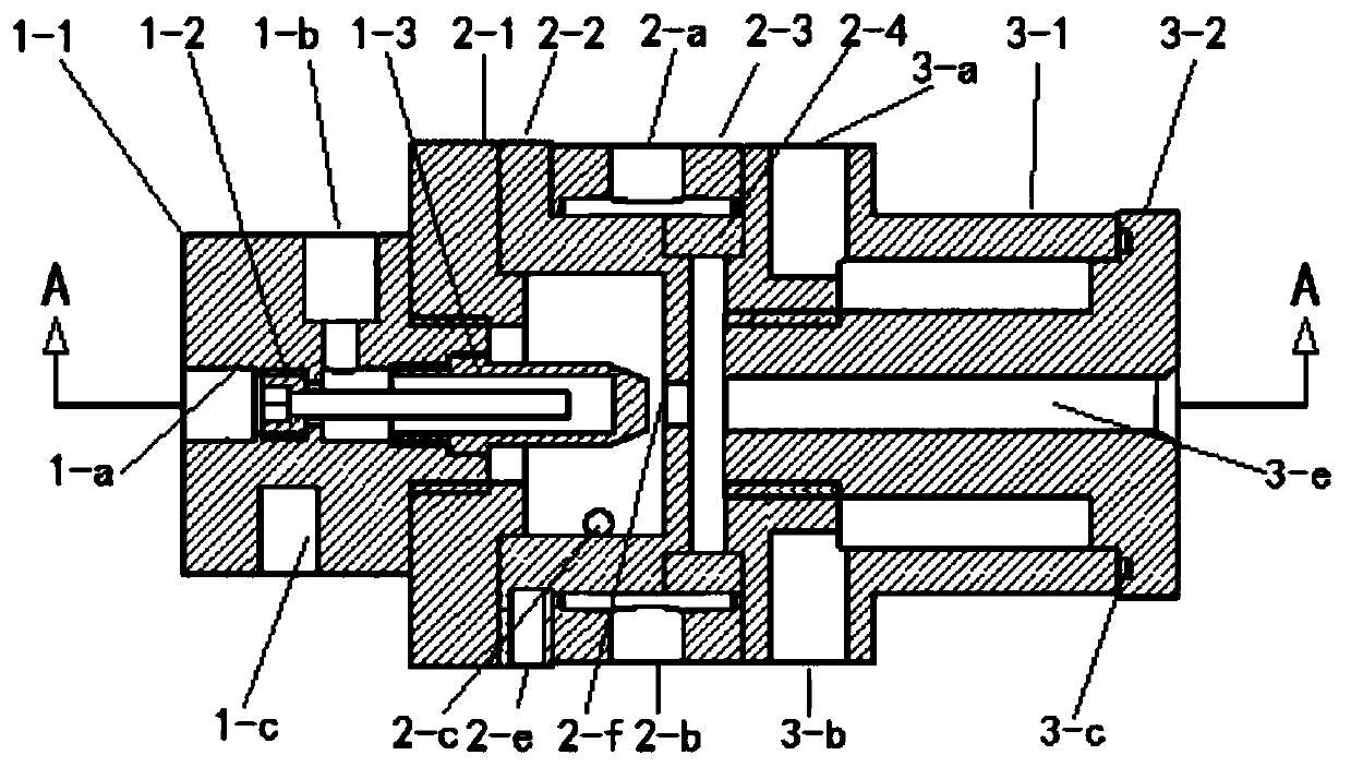
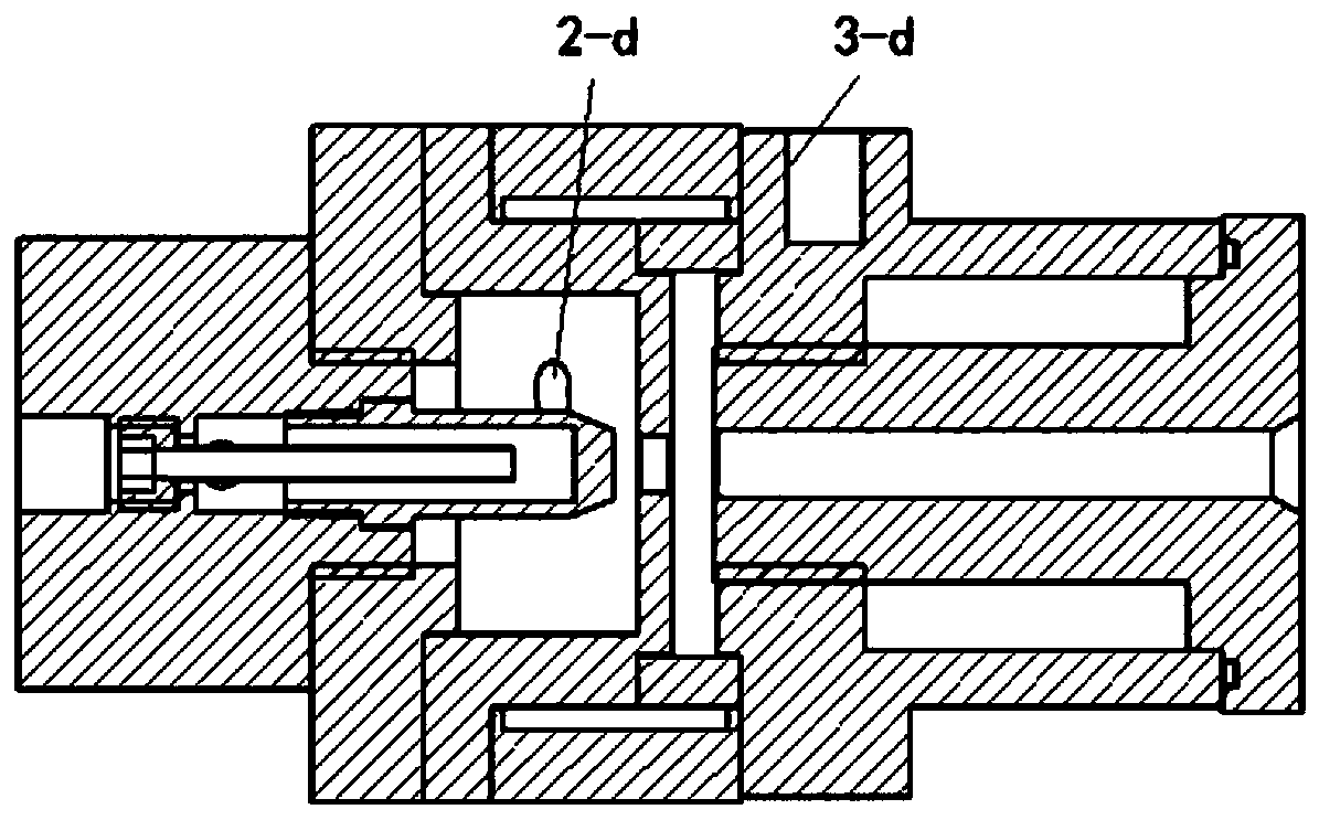
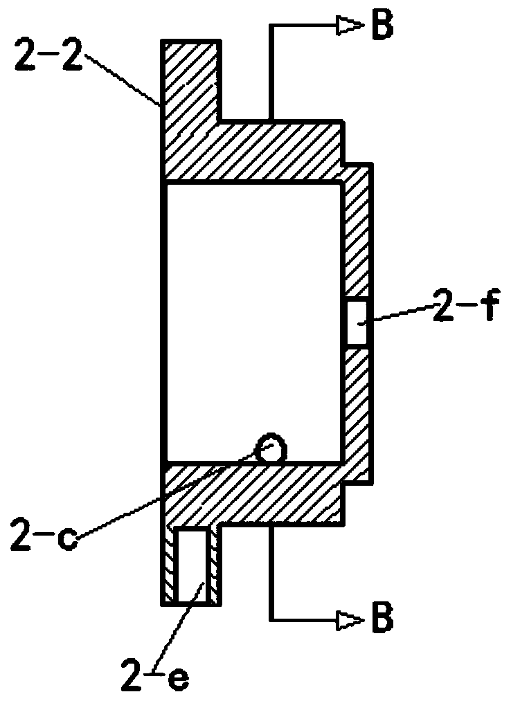
[0051] Such as figure 1 A specific implementation of the plasma generator shown includes a cathode 1, an arc starting anode 2, and an anode 3 that are coaxially connected in series in sequence, and the cathode 1 is provided with a cathode sleeve 1-1 and a cathode head 1-3 and a first cooling channel for cooling the cathode head 1-3, the anode 3 is provided with an anode casing 3-1, an anode lining 3-2 and a second cooling channel for cooling the anode lining 3-2, The arc-starting anode 2 includes: arc-starting anode lining 2-2, which is used to generate high-frequency voltage to break down the working gas to form plasma between the arc-starting anode lining 2-2 and the cathode head 1-3 after electrification, And pass to the anode 3 under the action of the gas to make the cathode 1 and the anode 3 conduct to form a stable plasma jet; the plasma generation chamber is located on the side of the arc starting anode lining 2-2 facing the cathode head 1-3, The arc starting anode 2 i...

Embodiment 2

[0064] Such as Figure 5 A specific implementation of the shown plasma destruction furnace includes: a destruction chamber formed around a refractory layer and a setter plate for accommodating the medium to be destroyed, the destruction chamber is provided with a gas outlet, and the setter The plate is located at the bottom of the destruction chamber; the plasma generator is used to deliver the plasma jet towards the destruction chamber; The gas cooling chamber is connected to a flue gas outlet, and the plasma destruction furnace is also provided with an air inlet connected to a gas supply system for generating compressed gas and a flue gas outlet connected to the flue gas cooling chamber.

[0065] Further, the refractory layer is covered with an insulating layer, the plasma generator is a DC non-contact plasma generator, and the required electric energy is provided by a DC plasma power supply.

[0066] During use: After the device is powered on, the gas supply system provide...

Embodiment 3

[0068] Such as Figure 6 A specific implementation of the plasma destruction system shown, the plasma destruction furnace, the flue gas cooling chamber, the flue gas filtration and purification room and the induced draft system are sequentially connected along the direction of the flue gas; the plasma destruction furnace is also provided with The air inlet communicates with the gas supply system for generating compressed gas and the flue gas outlet communicates with the flue gas cooling chamber. During use, the gas supply system provides compressed air for the plasma destruction furnace as the working gas of the plasma destruction furnace. The high-temperature flue gas in the air cooling chamber is mixed with room temperature air to cool down. The room temperature air can enter the flue gas cooling chamber by direct inhalation through the negative pressure generated by the induced draft system, or by direct air supply through the fan. After the flue gas is cooled, it directl...


PUM


Abstract

The invention relates to the technical field of waste treatment, and in particular to a plasma destruction system. The plasma destruction system comprises a plasma destruction furnace, a flue gas cooling chamber, a flue gas filtering purification chamber and an induced air system which sequentially communicate along the direction of flue gas; the plasma destruction furnace comprises a destructionchamber, a plasma generator, a gas inlet and a flue gas outlet, wherein the destruction chamber is surrounded by a refractory layer and a burning bearing plate, and is used for containing media to bedestructed; the destruction chamber is provided with an air outlet; the burning bearing plate is positioned at the bottom of the destruction chamber; the plasma generator is used for conveying plasmajet to the destruction chamber; the gas inlet communicates with a gas supply system for generating compressed gas; and the flue gas outlet communicates with the flue gas cooling chamber. The device has advantages of being simple in structure, small in size and wide in application range.

Description

technical field [0001] The invention relates to the technical field of waste treatment, in particular to a plasma destruction system and a destruction method. Background technique [0002] Confidential media refers to objects that store confidential information, such as paper, CD, magnetic disk, U disk, etc., generally classified into two categories: "magnetic media" and "paper media". Due to the need for confidentiality, the destruction methods for each type of media are also different. At present, there are many methods for processing secret-related media, and the processing methods applied to different secret-related media are also different. For paper materials, it can be processed by crushing, beating, incineration, etc. For example, paper shredders crush paper into fine paper scraps through a crushing device, so as to achieve the purpose of destroying paper. For hard magnetic media such as hard disks, they can be processed by degaussing, extrusion, crushing, inciner...

Claims


Application Information

Patent Timeline
Patent Type & Authority Applications(China)
IPC IPC(8): F23G5/10B01D46/00B01D53/32
CPCB01D46/00B01D53/32B01D2259/818F23G5/085F23G5/10F23G2204/201
Inventor 洪俊于林李鹏倪志良汪小知
Owner SUZHOU WEIMU INTELLIGENT SYST CO LTD
Why Eureka
Try Eureka