Replaceable laser unit and array thereof
A laser replacement technology, applied in the direction of lasers, laser devices, laser parts, etc., can solve problems such as difficult and accurate alignment, and achieve the effect of reducing difficulty and improving popularization rate
- Summary
- Abstract
- Description
- Claims
- Application Information
AI Technical Summary
Problems solved by technology
Method used
Image
Examples
Embodiment 1
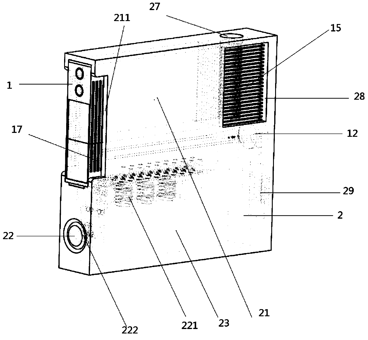
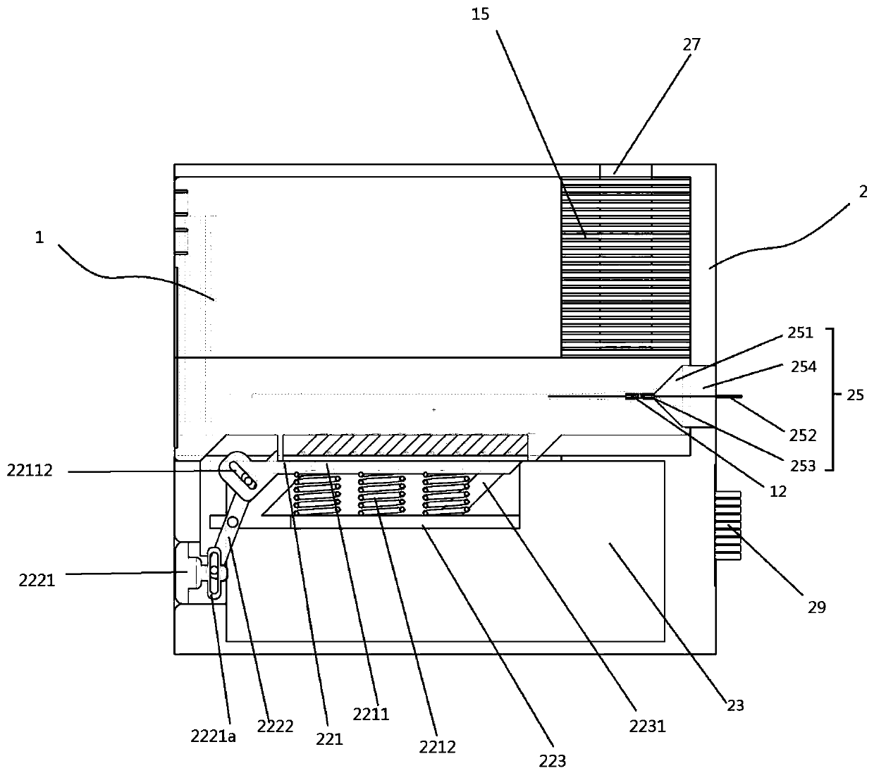
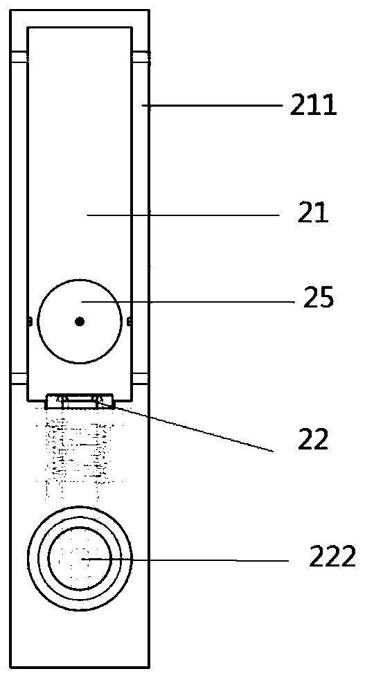
[0057] A replaceable laser unit such as Figure 1-12 As shown, it includes a casing 1 fixed with laser components and a casing 2 for clamping the casing 1; the casing 1 has a unique electrical interface 11 and several optical interfaces 12 docked with the casing 2; the The casing 1 can be extracted from the casing 2 and replaced with another casing containing laser components emitting lasers of different wavelengths. Since there are many drawings of the present invention, for unified identification, "front" refers to the attached Figure 1-12 The position of the insertion opening when the middle casing is inserted into the casing, that is, the position of the front panel of the casing is the front, and the position of the rear panel of the casing opposite to it is the rear. see details Figure 12 The coordinate system in , where the X-axis points to the front, the Y-axis points to the right, and the Z-axis points to the up.
[0058] Specifically, the chassis 2 includes a fi...
Embodiment 2
[0068] As a preference, the difference between this embodiment and the above-mentioned embodiment is that, as Figure 1-11 As shown, the upper panel of the fastening plate 2211 is provided with several cylindrical protrusions 24 whose axes are inclined backwards, and the corresponding lower panel of the casing 1 is provided with several columns with the same shape as the cylindrical protrusions 24. The cylindrical through groove 13; the cylindrical protrusion 24 passes through the card interface 212 upwards and snaps into the cylindrical through groove 13 under the action of the elastic component 2212;
[0069] Preferably, the engaging device 22 further includes a button assembly 222, when the button assembly 222 moves backward, it drives the fastening plate 2211 to move obliquely downward along the axial direction of the cylindrical protrusion 24, and the elastic assembly 2212 Switch from the natural state to the energy storage state, and the cylindrical protrusion 24 is sepa...
Embodiment 3
[0077] As a preference, the cylindrical protrusion 24 and the cylindrical through groove 13 are respectively provided with matching male and female electrical interfaces, and the cylindrical protrusion 24 passes upwards under the action of the elastic component 2212 The card interface 212 is snapped into the cylindrical through slot 13 to supply power to the laser element and perform auxiliary parameter adjustment of the laser element; preferably, the electrical interface of the cylindrical protrusion 24 passes through the The electrical output joint 29 is connected to the power supply and / or the parameter adjustment control device of the laser element, and the electrical interface 11 in the cylindrical through groove 13 is respectively connected to the power supply interface and / or power adjustment interface, wavelength adjustment interface, pulse adjustment interface inside the laser element. The interface and other parameters control the interface to connect directly;
[0078...
PUM
 Abstract
Description
Claims
Application Information
 - R&D
- Intellectual Property
- Life Sciences
- Materials
- Tech Scout
- Unparalleled Data Quality
- Higher Quality Content
- 60% Fewer Hallucinations
Browse by: Latest US Patents, China's latest patents, Technical Efficacy Thesaurus, Application Domain, Technology Topic, Popular Technical Reports.
© 2025 PatSnap. All rights reserved.Legal|Privacy policy|Modern Slavery Act Transparency Statement|Sitemap|About US| Contact US: help@patsnap.com


