Eureka AIR delivers breakthrough ideas for toughest innovation challenges, trusted by R&D personnel around the world.

Strong electromagnetic pulse multi-level protection device

A protection device, strong electromagnetic technology, applied in circuit devices, emergency protection circuit devices, emergency protection circuit devices for limiting overcurrent/overvoltage, etc. Can not play a comprehensive protection and other problems, to achieve the effect of increasing the scope of use, reducing the volume and reducing the cost

Pending Publication Date: 2019-11-12
SICHUAN SUNUP SCI & TECH
View PDF0 Cites 1 Cited by
  • Summary
  • Abstract
  • Description
  • Claims
  • Application Information

AI Technical Summary

Problems solved by technology

[0003] Existing protective equipment can be divided into power supply, data and antenna feeder according to their functions, and the power supply can be further divided into DC and AC. However, these protective equipment often have certain limitations and can only protect specific energy or spectrum. (Waveform) electromagnetic pulse protection, especially for fast pulses with a short rising edge time, cannot achieve a comprehensive protection effect, and the protection efficiency needs to be further improved; if the requirements for comprehensive protection of the system and equipment are to be met, it must be in each system 1. A single-function electromagnetic pulse protection module, lightning protection module and EMI filter module are installed in the equipment. If these equipment are installed at the same time, the weight and size will be greatly affected, which is not conducive to the performance of the system and equipment.
However, in modern electronic technology, various systems and equipment require miniaturization, integration, and light weight, so the above protection scheme is not very practical

Method used


Image

  • Strong electromagnetic pulse multi-level protection device
  • Strong electromagnetic pulse multi-level protection device
  • Strong electromagnetic pulse multi-level protection device

Examples


Embodiment 1

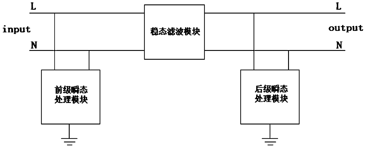
[0034] A strong electromagnetic pulse multi-level protection device provided by a preferred embodiment of the present invention includes a phase line L, a neutral line N, a ground line PE, a pre-stage transient processing module, a post-stage transient processing module, and a steady-state filter module , the phase line L is divided into the first phase line L1, the second phase line L2, and the third phase line L3, and the phase line L is sequentially connected to the front-stage transient processing module, the steady-state filter module and the post-stage transient processing module module, the neutral line N is sequentially connected to the pre-stage transient processing module, the steady-state filter module and the subsequent transient processing module, and the ground wire PE is connected to the pre-stage transient processing module and the subsequent transient processing module.

[0035] Existing protective equipment can be divided into power supply, data and antenna fe...

Embodiment 2

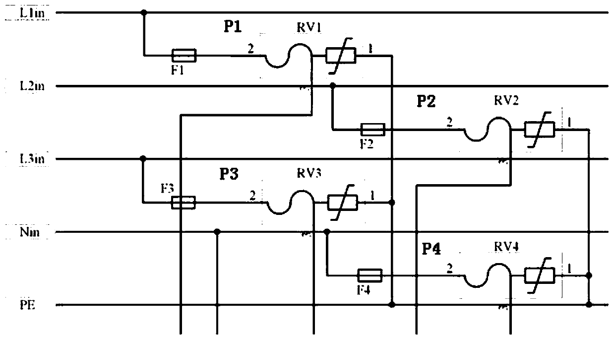
[0038] In this embodiment, on the basis of Embodiment 1, the front-stage transient processing module includes a first protection unit P1, a second protection unit P2, a third protection unit P3, and a fourth protection unit P4, each of which has It includes a high-energy transient protection module F and a high-energy transient discharge module RV, one end of the high-energy transient protection module F is the input end of the protection unit, and the other end of the high-energy transient protection module F is connected to the high-energy transient discharge module RV. One end of the discharge module RV is connected, and the other end of the high-energy transient discharge module RV is the output end of the protection unit; the input end of the first protection unit P1, the input end of the second protection unit P2 and the third protection unit P3 The input terminals of the first phase line L1, the second phase line L2 and the third phase line L3 are respectively connected;...

Embodiment 3

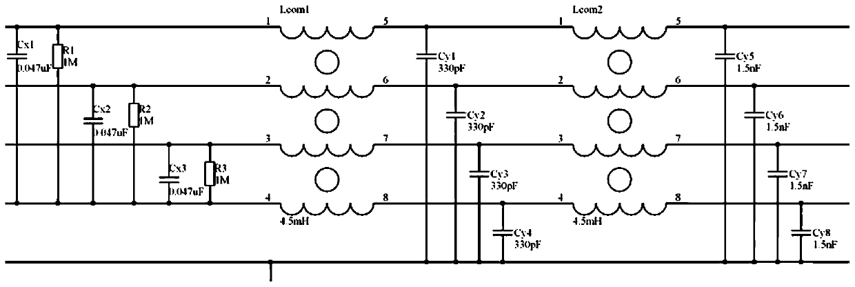
[0044] In this embodiment, on the basis of Embodiment 1, the steady-state filter module includes a first capacitor group, a second capacitor group, a resistor group, and an inductance group, and the first capacitor group includes a capacitor C x 1. Capacitance C x 2. Capacitance C x 3. The second capacitor bank includes capacitor C y 1. Capacitance C y 2. Capacitance C y 3. Capacitance C y 4. Capacitance C y 5. Capacitance C y6. Capacitance C y 7. Capacitance C y 8. The resistance group includes resistor R1, resistor R2, and resistor R3, and the inductance group includes inductor L com 1. Inductance L com 2. The inductance L com 1 and the inductance L com 2 are composed of four windings and a magnetic ring;

[0045] The first phase line L1 is sequentially connected with the capacitor C x 1 input, resistor R1 input, inductor L com 1. Capacitance C y The input terminal of 1, the inductance L com 2. Capacitance C y 5 connected to the input; the second phase line ...


PUM


Abstract

The invention discloses a strong electromagnetic pulse multi-level protection device and belongs to the field of electromagnetic pulse protection. The device disclosed in the invention comprises a phase line L, a neutral line N, a ground line PE, a pre-stage transient processing module, a post-stage transient processing module and a steady-state filtering module. The phase line L is sequentially connected to the pre-stage transient processing module, the steady-state filtering module and the post-stage transient processing module. The neutral line N is sequentially connected to the pre-stage transient processing module, the steady-state filtering module and the post-stage transient processing module. The ground line PE is connected with the pre-stage transient processing module and the post-stage transient processing module. The multi-level protection device disclosed in the invention can be used for delaying fast pulses, reducing rising edge time of the fast pulses, and ensuring thatsufficient time is left for a back stage system to process the pulses; functions of electromagnetic pulse protection equipment are integrated, and therefore the protection device can be adapted to a variety of application scenarios; excellent protection effects can be exerted on systems low in endurance capacity.

Description

technical field [0001] The invention belongs to the field of electromagnetic pulse protection, and relates to a multi-stage protection device for strong electromagnetic pulses. Background technique [0002] In modern society, various electromagnetic pulses generated by nature and man-made, such as lightning electromagnetic pulse, nuclear pulse (high-altitude nuclear electromagnetic pulse), high-power microwave, ultra-wideband, internal surge, clutter harmonics and Strong electromagnetic pulse interference, etc., the interference is more and more frequent, and damages sensitive electronic systems and equipment through the ultra-strong transient pulse generated; with the development of science and technology, advanced electronic equipment uses large-scale integrated circuits in large quantities The larger the size, the more sensitive the electronic device and the more likely it is to be disturbed by electromagnetic pulses. Therefore, it is imperative to carry out comprehensiv...

Claims


Application Information

Patent Timeline
IPC IPC(8): H02H9/02H02H9/04H02H3/08H02J3/01
CPCH02H3/08H02H9/02H02H9/04H02J3/01Y02E40/40
Inventor 郑亦菲陈兵李宣庆
Owner SICHUAN SUNUP SCI & TECH
Why Eureka
Eureka Blog
Learn More