
Porous membrane for membrane distillation, and method for operating membrane distillation module

A technology of membrane distillation and components, applied in chemical instruments and methods, membranes, pervaporation, etc., can solve the problems of unclear surface state, water treatment capacity of membrane distillation components or membrane distillation devices, time stability, transportability, and handling properties Lowering and other issues

Active Publication Date: 2019-11-15
ASAHI KASEI KK
View PDF13 Cites 1 Cited by
  • Summary
  • Abstract
  • Description
  • Claims
  • Application Information

AI Technical Summary

Problems solved by technology

[0022] In addition, in addition to wetting, the present inventors have also found the following problem: In membrane distillation, a solute (such as NaCl crystal) in an undissolved state is formed on the permeation side surface and inside (membrane thickness portion) of the porous membrane. The phenomenon of precipitation and residue (hereinafter referred to as "salt permeation") reduces the water treatment capacity, stability over time, transportability, handling properties, etc. of the membrane distillation module or membrane distillation device
The porous membrane described in Patent Document 3 does not mention its structure, especially its internal structure, and its surface state is also unclear, so there is room for improvement in terms of wetting and inhibition of salt permeation

Method used


Image

  • Porous membrane for membrane distillation, and method for operating membrane distillation module
  • Porous membrane for membrane distillation, and method for operating membrane distillation module
  • Porous membrane for membrane distillation, and method for operating membrane distillation module

Examples


Embodiment 1

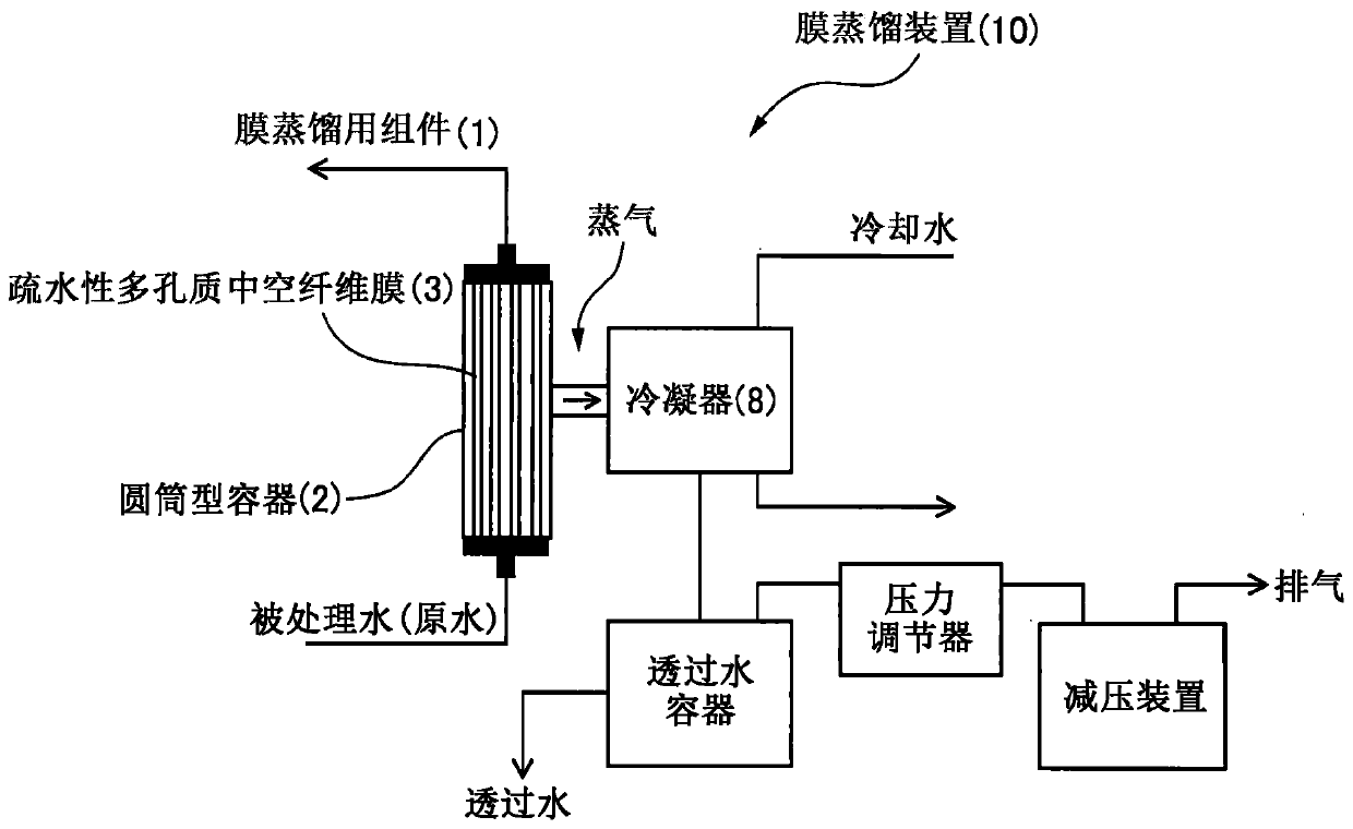
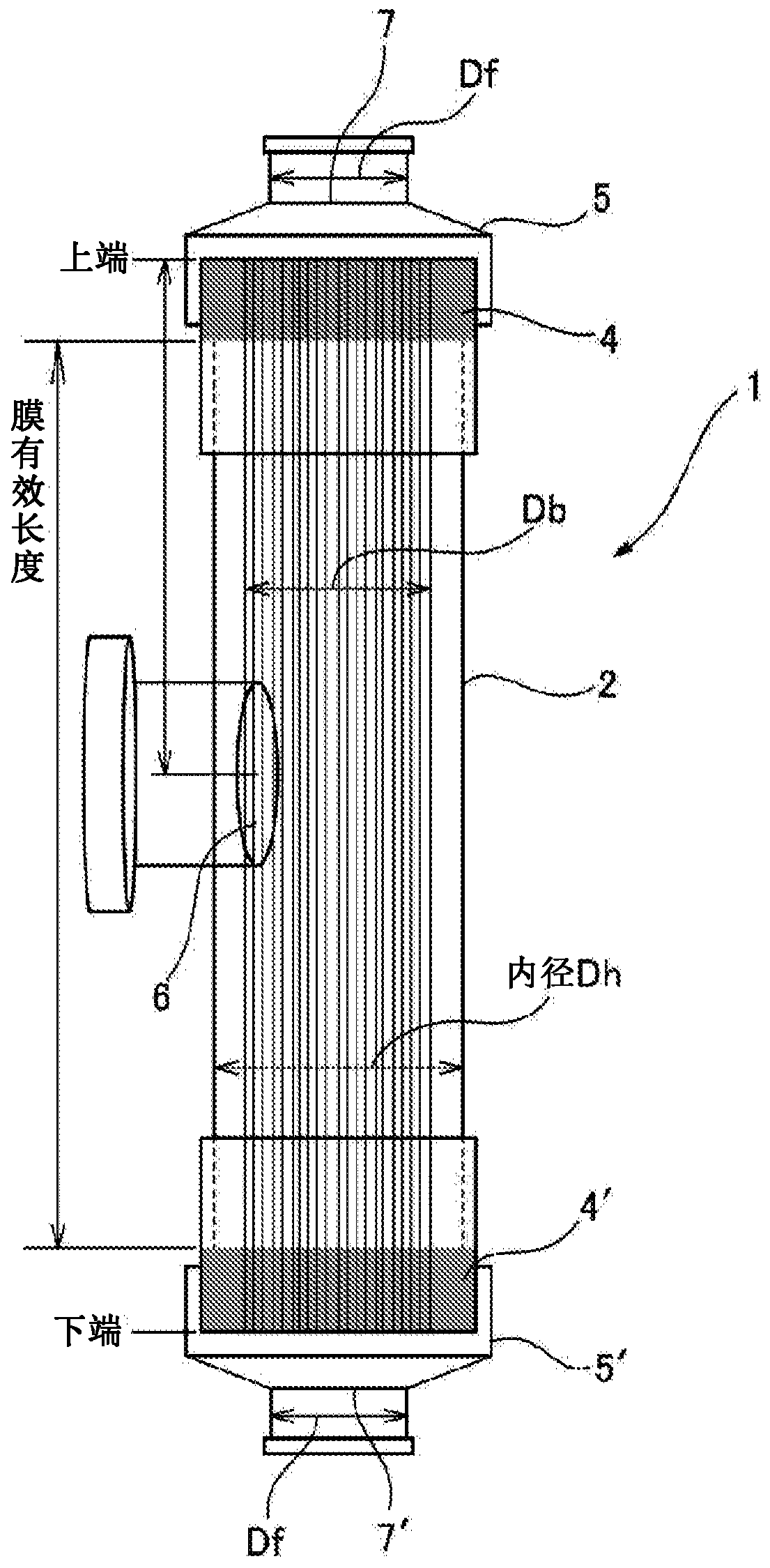
[0691] Put 4,200 polyvinylidene fluoride hollow fiber membranes with an outer diameter of 1.22 mm, an inner diameter of 0.66 mm, and a film thickness of 280 μm in a cylindrical container made of polysulfone with an inner diameter of 128 mm, and bond the hollow fiber membranes to the cylinder with epoxy resin. The gap of the type container was fixed, and a membrane module for membrane distillation with an effective membrane length of 86 mm was produced. In addition, 360 stainless steel tubes having an inner diameter of 1 mm, an outer diameter of 1.2 mm, and an effective length of 220 mm were housed in the same container as the above-mentioned cylindrical container to produce a condenser. Such as figure 1 As shown, the module for membrane distillation and the condenser were connected to each other at one side opening. At this time, the shortest distance between the outer surface of the hollow fiber membrane in the membrane distillation module and the outer surface of the stainl...

Embodiment 2

[0697] Membrane distillation was performed in the same manner as in Example 1 except that 4400 hollow fiber membranes were used. The structural characteristics of the membrane distillation module used, the operating conditions of the membrane distillation, and the results are shown in Table 1 below. The flux is 14.6kg / m 2 / hr, the permeated water production efficiency was 2.7%, and the conductivity of the obtained permeated water varied in the range of 0.1 to 0.2 μS / cm.

Embodiment 3

[0699] Membrane distillation was performed in the same manner as in Example 1 except that 4600 hollow fiber membranes were used. The structural characteristics of the membrane distillation module used, the operating conditions of the membrane distillation, and the results are shown in Table 1 below. The flux is 13.4kg / m 2 / hr, the permeated water production efficiency was 2.6%, and the conductivity of the obtained permeated water varied in the range of 0.1 to 0.2 μS / cm.


PUM

PropertyMeasurementUnit
Apertureaaaaaaaaaa
Lengthaaaaaaaaaa
Apertureaaaaaaaaaa

Abstract

A membrane distillation device, provided with a membrane distillation module including a plurality of hydrophobic porous hollow fiber membranes, and a condenser for condensing water vapor extracted from the module. The average pore diameter of the porous hollow fiber is 0.01-1 microns. The filling ratio of the porous hollow fiber of the membrane distillation module is 10-80%, and the pressure condition for the membrane distillation is equal to or greater than 1 kPa and equal to or less than the saturated vapor pressure of water at the temperature of the water being treated.

Description

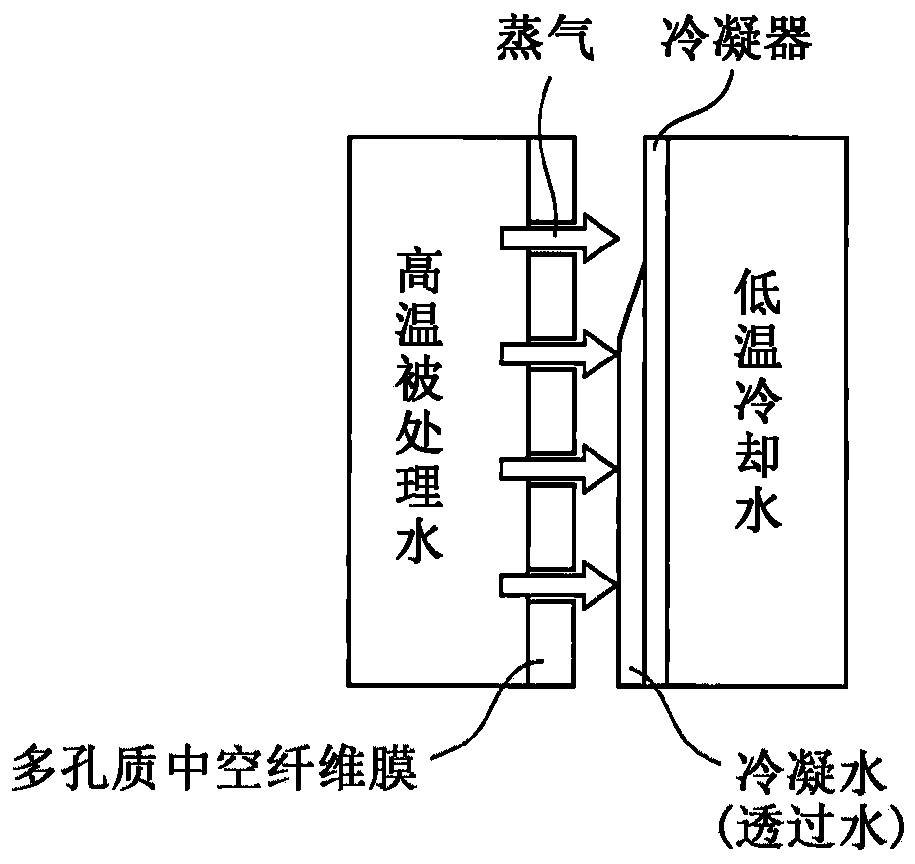
technical field [0001] The present invention relates to a module for membrane distillation and a membrane distillation apparatus including the module for membrane distillation. More specifically, the present invention relates to a membrane distillation module containing two or more hydrophobic membranes having through holes in a cylindrical container and a membrane distillation apparatus using the membrane distillation module. In the bundle of porous hollow fiber membranes, the water to be treated is passed inside the hollow fiber membranes, and the water vapor coming out from the outside is cooled and condensed, and recovered as permeated water. Background technique [0002] The membrane distillation (Membrane Distillation (MD)) method is the following method: using a hydrophobic porous membrane that allows only water vapor in the water to be treated to pass through, the heated high-temperature water to be treated (hereinafter also referred to as raw water) The water vapor...

Claims


Application Information

Patent Timeline
IPC IPC(8): B01D69/02B01D61/36B01D65/02B01D65/06B01D69/08
CPCB01D61/364B01D63/02B01D69/12B01D2325/02B01D2325/38B01D67/0088B01D69/02B01D63/033B01D61/366B01D61/368B01D69/081B01D63/026B01D65/02B01D69/1213B01D71/261B01D71/262C02F1/447B01D2325/02833B01D2325/02834B01D2325/24B01D2325/20B01D2321/16B01D61/3641B01D63/031
Inventor 桥本知孝新井裕之长田一人久保田昇竹泽浩气大豊武彦
Owner ASAHI KASEI KK
Learn More