Manufacturing method and manufacturing system for solar cell back plate

A technology of solar cells and manufacturing methods, applied in chemical instruments and methods, circuits, photovoltaic power generation, etc., can solve problems such as complex production process of solar cell backplanes, hidden dangers of production safety, threats to personal health, etc., and achieve good operability, Excellent solvent resistance and excellent chemical resistance

Pending Publication Date: 2019-11-19
WUXI LAIEN TECH
View PDF8 Cites 2 Cited by
  • Summary
  • Abstract
  • Description
  • Claims
  • Application Information

AI Technical Summary

Problems solved by technology

[0006] In order to solve the above-mentioned problems in the prior art, the object of the present invention is to provide a method for manufacturing a solar battery backplane, which can overcom...

Method used


Image

  • Manufacturing method and manufacturing system for solar cell back plate
  • Manufacturing method and manufacturing system for solar cell back plate
  • Manufacturing method and manufacturing system for solar cell back plate

Examples


Embodiment 1

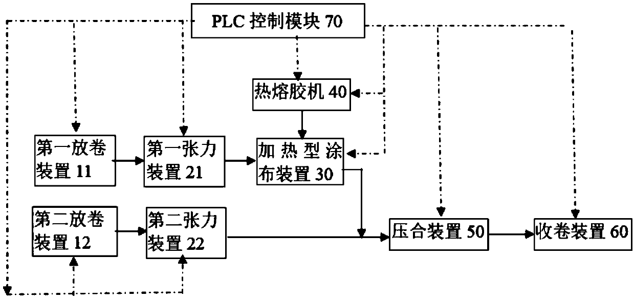
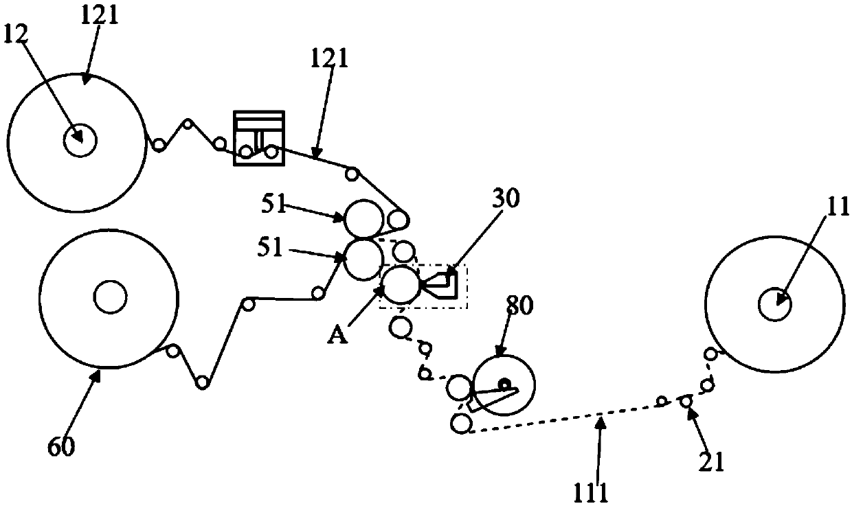
[0059] Combine figure 2 As shown, the first unwinding device 11 and the second unwinding device 12 are respectively installed with the first film material 111 and the second film material 121 in the roll, and the first film material 111 passes through the first tension device 21 to keep the film material flat. The wrinkles are then passed through a pretreatment device 80 to remove static electricity and dust on the surface of the first membrane 111. After the first film 111 passes through the first tension device 11 and the pretreatment device 80, it then passes between the heating type coating device 30 and the pressure roller A, and the heating type coating device 30 faces the surface of the first film 111. Coating reactive hot melt adhesive heated into a fluid state. The heating type coating device 30 is connected to a hot melt glue machine (not shown in the figure) through a glue pipe. The hot melt glue machine is continuously heated to produce a fluid state of reactive ho...

Embodiment 2

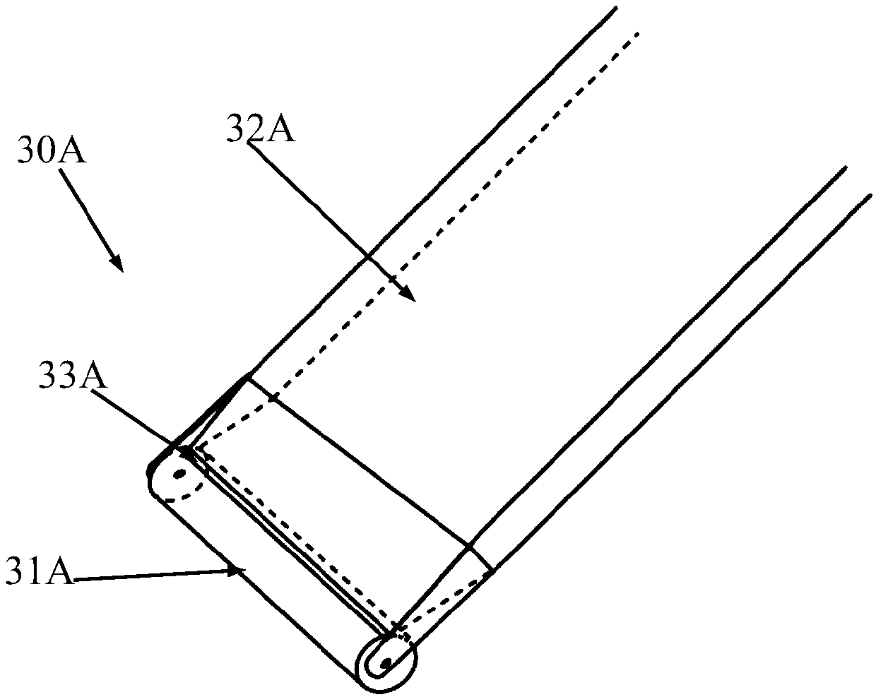
[0065] The only difference between Example 2 and Example 1 is that the heating-type coating device 30 in Example 1 is specifically selected as a heating non-marking scraper 30A with a rotating flat round bar, while in Example 2 the heating-type coating device The device 30 is implemented as a combination of a scraper 31 and a heated mesh roller 32, namely figure 2 Replace the part in the dashed box with Figure 4 The structure shown.

[0066] Combine Figure 4 ~ Figure 5 As shown, the heating-type coating device 30 is composed of a doctor blade 31 and a heating-type dot-shaped drum 32 arranged oppositely, and the heating-type dot-shaped drum 32 is tangent to the pressing wheel A. Before starting the manufacturing system of this embodiment, the hot melt glue machine is turned on, and the gap between the scraper 31 and the heated mesh roller 32 is adjusted to control the amount of glue. First, turn on the heating system matching the heating type mesh roller 32 and the scraper 31,...


PUM


Abstract

The invention relates to a manufacturing method and a manufacturing system for a solar cell back plate. The method is to use a reactive hot-melt adhesive to composite a first film material and a second film material into one body by pressing. The manufacturing system includes a heating type coating device and a hot-melt adhesive machine connected to the heating type coating device. The hot-melt adhesive machine conveys the reactive hot-melt adhesive heated to a fluid state to the heating type coating device. Compared with the prior art, the manufacturing method of the invention does not need the addition of a solvent to prepare the adhesive, no solvent volatilization exists in the compounding process, and drying process and drying equipment are not needed, which can reduce the energy consumption and the production cost, reduce the land occupation area of the equipment and improve the production efficiency and the product quality. The manufactured back plate has good weatherability, which prevents the back plate from peeling off and effectively prolongs the service life of a solar cell.

Description

Technical field [0001] The invention relates to a manufacturing method and a manufacturing system of a backplane of a solar battery pack. Background technique [0002] The solar backsheet is located on the back of the solar panel, which protects and supports the cells, and requires reliable insulation, water resistance, and aging resistance. The composite solar cell back sheet is made of a PET polyester film with a middle layer as a base, and a fluorine-containing film is laminated on the inner and outer sides with an adhesive (some manufacturers also use a non-fluorine PE layer for the inner layer to reduce costs). Fluorine film is mainly divided into two categories, one is PVF film (referred to as T film), also known as polyvinyl fluoride film, represented by DuPont’s Tedler PVF film; the other is PVDF film (referred to as K film), namely Polyvinylidene fluoride film. [0003] In order to ensure the reliability of the adhesion between the various layers of the solar backplane, ...

Claims


Application Information

Patent Timeline
IPC IPC(8): B32B37/12B32B37/10H01L31/049
CPCB32B37/1207B32B37/1284B32B37/10H01L31/049B32B2037/123B32B2037/1215Y02E10/50
Inventor 张来
Owner WUXI LAIEN TECH
Why Eureka
Try Eureka