Rare earth electrolytic tank for producing rare earth and alloys thereof

An electrolytic cell and rare earth technology, which is applied in the electrolysis process, electrolytic components, electrodes, etc., can solve the problems of difficulty in controlling anode current density and pole distance, difficulty in the implementation of industrialized production of electrolytic cells, and reducing the contact area between metal and electrolyte. Conducive to purification, recycling, high-efficiency production, and energy-saving production

Active Publication Date: 2019-11-22
GUIZHOU BRANCH CHINA ALUMINUM IND
View PDF4 Cites 7 Cited by
  • Summary
  • Abstract
  • Description
  • Claims
  • Application Information

AI Technical Summary

Problems solved by technology

The electrolytic cell invented by this patent achieves the purpose of low anode current density and high cathode current density. The metal groove is designed at the bottom of the electrolytic cell to reduce the contact area between the metal and the electrolyte, which is beneficial to improve the current efficiency, but the design of the anode structure is easy to cause the distribution of the anode current. Uneven, difficult to control anode current density and pole distance
Patent CN105441987A discloses a rare earth molten salt electrolytic cell for producing rare earth metals and alloys with a liquid cathode. The structure is that the anode and cathode are parallel and vertically inserted into the electrolyte, and the liquid metal in the electrolytic cell is used as the cathode. Invented the water-cooling system for welding the inner and outer sides of the electrolyzer to make the rare earth molten salt crust on the surface of the inner tank to form a crust protective layer. It is difficult to implement the industrial production of the electrolytic tank, and the temperature outside the inner tank of the electrolytic tank is relatively high, posing a great safety hazard
In addition, the upper part of the electrolytic cell is open, which will cause a large amount of heat to be lost by radiation from the upper part, and the consumption of graphite anodic oxidation is serious

Method used


Image

  • Rare earth electrolytic tank for producing rare earth and alloys thereof
  • Rare earth electrolytic tank for producing rare earth and alloys thereof
  • Rare earth electrolytic tank for producing rare earth and alloys thereof

Examples


Embodiment Construction

[0025] The present invention will be described in detail below in combination with specific embodiments.

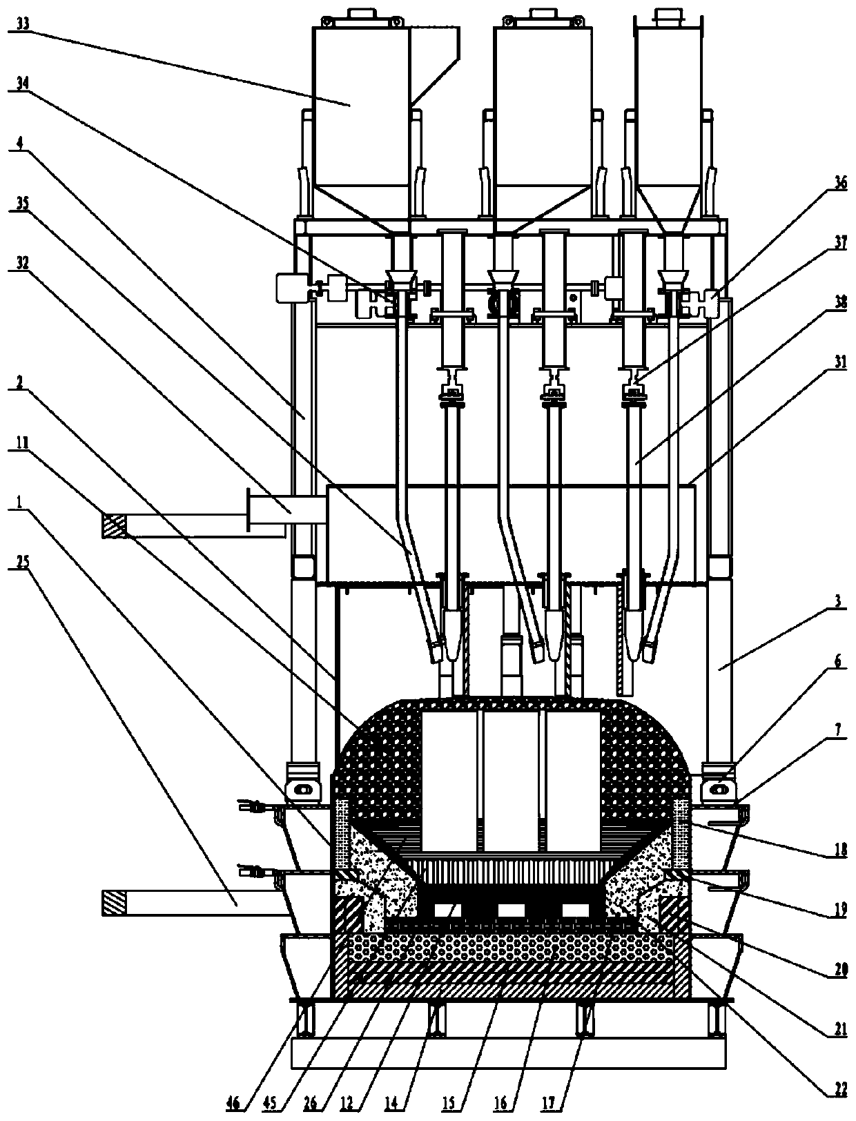
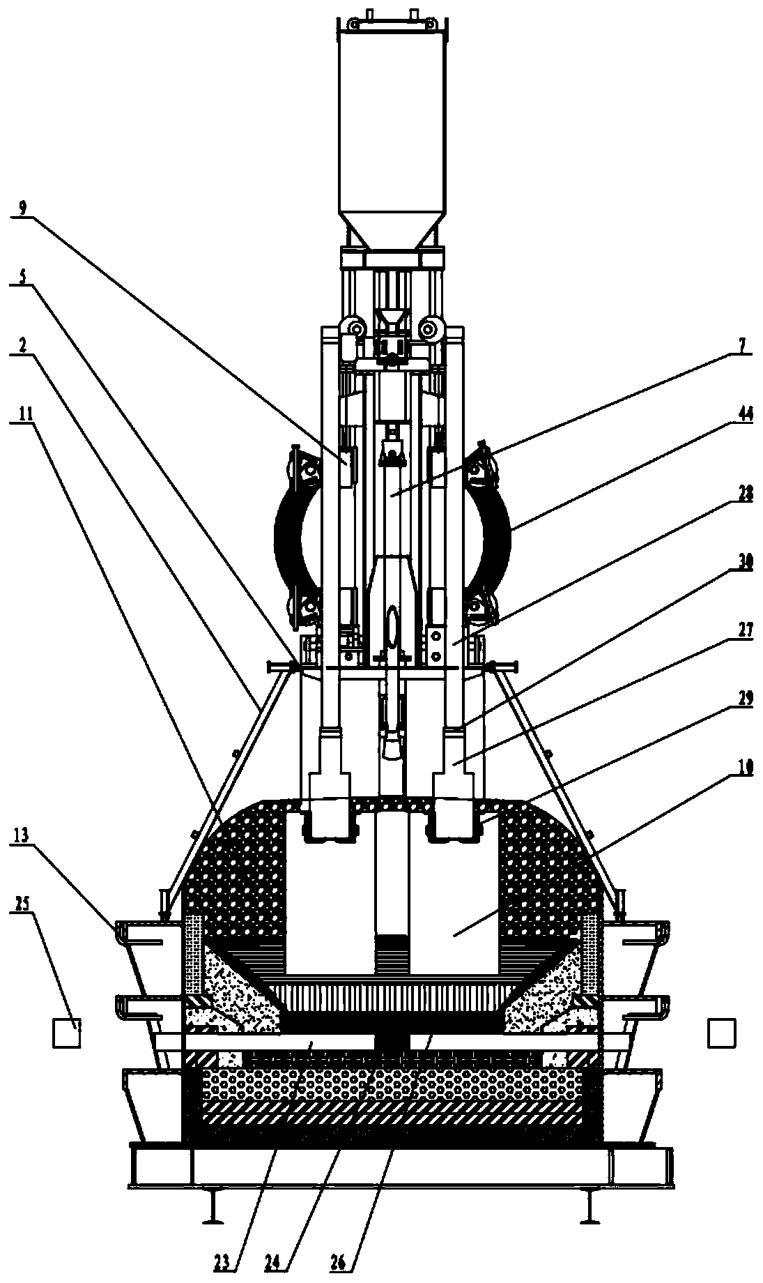
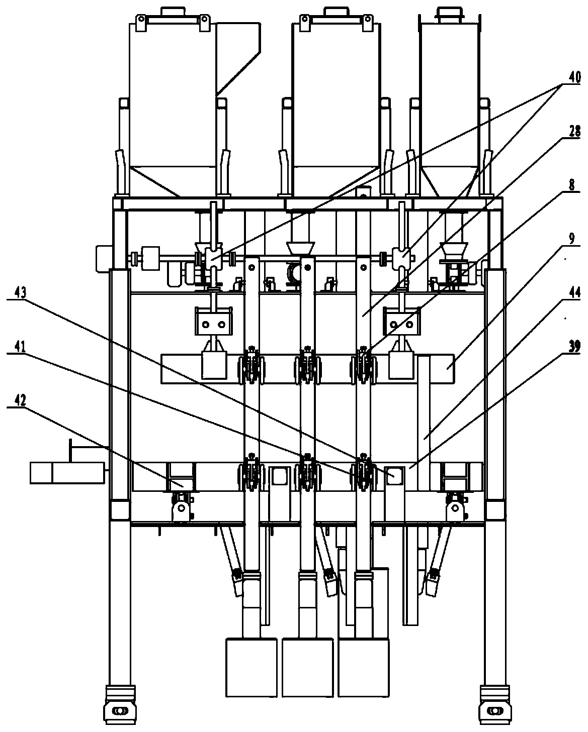
[0026] see figure 1 , figure 2 and image 3 , the rare earth electrolytic cell of this embodiment includes a cell shell, a cell liner, a cathode group structure, an anode assembly, a column girder frame, a cell cover plate, a blanking system, a shell breaking system, a gas collection system, an anode lifting and a bus transfer system And intelligent slot control system. The electrolysis current of the rare earth electrolyzer is 10-200kA, the electrolyte system used is REF3 (86-97%)-LiF (3-14%), the electrolysis temperature is 850-1250°C, and the anode current density is 0.7-2.0A / cm2, The cathode current density is 0.6-3.2A / cm2.

[0027] The tank shell 1 is a rectangular structure welded with steel plates, and the sides are welded with a coaming plate, a tank edge plate 7 , a stiffener plate and a cooling air duct 13 .

[0028] The trough cover plate 2 is a double-la...


PUM


Abstract

The invention discloses a rare earth electrolytic tank for producing rare earth and alloys thereof. The rare earth electrolytic tank comprises an electrolytic tank body, a cathode group structure, ananode group structure and a tank upper portion structure, wherein the electrolytic tank body comprises a tank shell and a tank lining, the tank upper portion structure comprises a vertical column girder frame, a material feeding system, a shell ramming system, an anode lifting and busbar switching system and a tank hood plate, the upper end of the anode group structure is connected with the anodelifting and busbar switching system, anode blocks at the lower end are vertically inserted in electrolyte inside the tank body, the parts, exposed outside the electrolyte level face, of the anode blocks are covered by an anode covering material, the anode lifting and busbar switching system is used for adjusting the polar distance between the anode blocks and the cathode group structure, the material feeding system, the shell ramming system and the anode lifting and busbar switching system are integrated into an intelligent tank control system, the upper edge of the tank hood plate is connected with the edge of the side portion of a horizontal hood plate, and the lower edge of the tank hood plate is connected with the upper surface of the tank shell to realize closeness of the electrolytictank. By means of the rare earth electrolytic tank for producing the rare earth and the alloys thereof, rare earth electrolytic tank automatic continuous, high-efficiency, low-energy-consumption, low-cost and clean production is realized.

Description

technical field [0001] The invention belongs to the technical field of rare earth molten salt electrolysis, and in particular relates to a rare earth electrolytic cell for producing rare earth and its alloys. Background technique [0002] At present, the industrial production of rare earth metals mainly adopts the oxide electrolysis method of fluoride molten salt system, using rare earth oxides as raw materials and rare earth fluorides as electrolytes. The electrolytic cell is a cathode and anode structure with a graphite furnace body. The single tungsten / molybdenum rod cathode is inserted into the electrolyte from the center of the tank or the multi-tungsten / molybdenum rod cathode is inserted into the electrolyte from the central axis. The graphite anode plate surrounds the cathode, and the furnace bottom crucible accepts the metal. For electrolytic production, the voltage of the conventional cell is 9-11V, the current efficiency is 60-70%, the metal yield is 94-95%, and th...

Claims


Application Information

Patent Timeline
Patent Type & Authority Applications(China)
IPC IPC(8): C25C3/34C25C7/00C25C7/02C25C7/06
CPCC25C3/34C25C7/00C25C7/025C25C7/06
Inventor 张亚楠柴登鹏张芬萍李静侯光辉于强刘彦辉白卫国刘秀
Owner GUIZHOU BRANCH CHINA ALUMINUM IND
Why Eureka
Try Eureka