
Special-shaped separated heat pipe waste heat recovery and evaporation device for passive ORC system

A separate heat pipe and waste heat recovery technology, applied in the field of expansion machine work, can solve the problems of discontinuity, the compactness of the gravity-driven power circulation system, and the large fluctuation of the output shaft power, etc., to achieve simple layout, waste heat recovery and heat. Efficient transfer avoidance, less parts effect

Active Publication Date: 2019-12-03
NANJING UNIV OF TECH +1
View PDF8 Cites 1 Cited by
  • Summary
  • Abstract
  • Description
  • Claims
  • Application Information

AI Technical Summary

Problems solved by technology

However, for the pumpless ORC system, there are large fluctuations and discontinuities in the output shaft power, and the gravity-driven power cycle has a great impact on the compactness of the system. Therefore, a separate heterogeneous heat pipe evaporator with dual cooling sections is proposed. The evaporator system, the double cooling section evaporator can effectively control the heat in the heat pipe and the evaporation and condensation of the organic working medium in the sealed energy storage box through the regulating valve, and accurately complete the time coupling of the ORC system

Method used


Image

  • Special-shaped separated heat pipe waste heat recovery and evaporation device for passive ORC system
  • Special-shaped separated heat pipe waste heat recovery and evaporation device for passive ORC system
  • Special-shaped separated heat pipe waste heat recovery and evaporation device for passive ORC system

Examples


Embodiment Construction

[0041] specific implementation plan

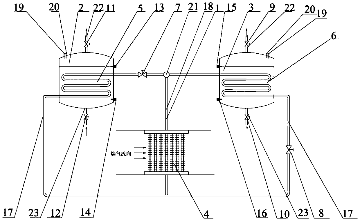
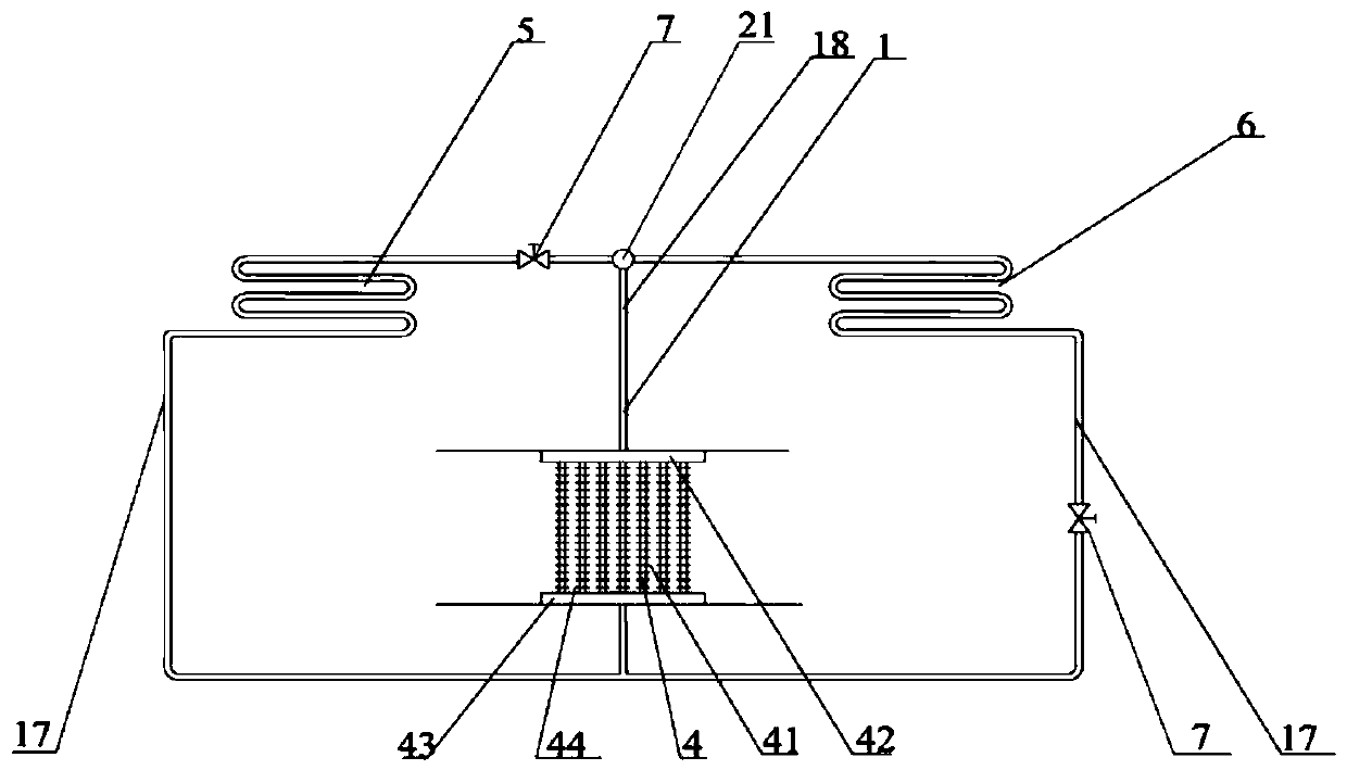
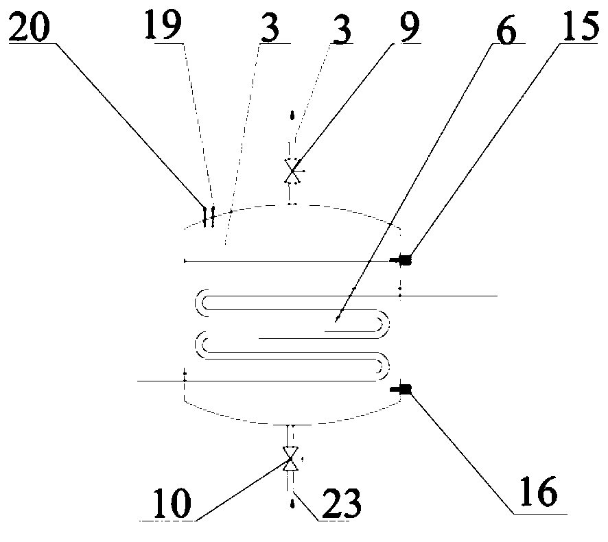
[0042] Such as Figure 1-5 As shown, a special-shaped separated heat pipe waste heat recovery evaporation device for passive ORC system is composed of double cold section special-shaped separated heat pipe 1, energy storage closed tank A2, energy storage closed tank B3, finned elliptical heat pipe evaporation section Tube bundle 4, heat pipe cooling section coil A5, heat pipe cooling section coil B6, mass flow regulating valve 7, resistance regulating valve 8, organic working medium steam outlet valve-9, organic working medium liquid inlet valve-10, organic working medium steam Outlet valve two 11, organic working fluid inlet valve two 12, high liquid level sensor one 13, low liquid level sensor one 14, high liquid level sensor two 15, low liquid level sensor two 16, liquid descending pipe 17, steam ascending pipe 18. Pressure gauge 19, thermometer 20, steam riser branch pipe 21, organic working medium steam outlet pipeline 22 and organic...


PUM


Abstract

The invention discloses a special-shaped separated heat pipe waste heat recovery and evaporation device for a passive ORC system. According to the device, the low-temperature waste heat flue gas is used for scouring a pipe bundle of an evaporation section of an elliptical heat pipe with fins, so that a working medium in the pipe is vaporized, rises and is gathered into a gas collection pipe. The flow of the heat pipe working medium entering a heat pipe cooling coil A and a heat pipe cooling coil B is adjusted through an adjusting valve, the heating of the organic working mediums in an energy storage closed tank A and an energy storage closed tank B is achieved through the working medium condensation heat release, and the condensed heat pipe working mediums flow back to the heat pipe evaporation section along a descending pipe. According to the device, when one closed tank is in a closed heating, boosting, vaporizing and heat absorbing process, the other closed tank is in a constant-pressure and constant-temperature vaporized steam discharging process, and the running time of the two processes is kept consistent in one period. According to the device, the leakage and harm of the organic working mediums caused by the flue gas are avoided, the heat transfer performance of the heat pipe is improved through the elliptical fin heat pipe structure, the flue gas side resistance and themanufacturing cost of the heat pipe are reduced, and the reliability, safety, stability and heat efficiency of the whole system are effectively improved.

Description

technical field [0001] The present invention is a kind of heat source which utilizes middle and low temperature waste heat flue gas, special-shaped double cooling section separated heat pipe as heat transfer element, and uses the long-distance transport energy and one-way flow characteristics of the separated heat pipe to heat the organic working medium, so that the organic working medium Mass pressurized vaporization provides kinetic energy for saturated steam to push the expander to do work, and realizes self-pressurized waste heat recovery device for power generation with medium and low temperature waste heat organic working fluid, which belongs to the field of waste heat recovery and heat pipe heat exchanger. Background technique [0002] Because the gaseous medium and low temperature waste heat flue gas often contains ash and corrosive gases, it is easy to cause heat exchanger leakage, and the conventional tube-fin flue gas waste heat heat exchanger is large in size and ...

Claims


Application Information

Patent Timeline
Patent Type & Authority Applications(China)
IPC IPC(8): F28D15/02F01D15/10F01K25/08F01K27/00F22B1/18F23J15/06
CPCF28D15/02F01K27/00F01K25/08F01D15/10F22B1/1807F23J15/06Y02E20/30
Inventor 周剑秋陈琦璐苏磊张钧波庄志黄骏峰张中男
Owner NANJING UNIV OF TECH
Learn More