A cement kiln flue gas denitrification process

A cement kiln and denitrification technology, which is applied in gas treatment, separation methods, and dispersed particle separation, etc., can solve problems such as affecting production progress, low denitrification efficiency, and flue gas backflow

Active Publication Date: 2021-11-30
冀东水泥重庆合川有限责任公司
View PDF6 Cites 0 Cited by
  • Summary
  • Abstract
  • Description
  • Claims
  • Application Information

AI Technical Summary

Problems solved by technology

[0002] A large amount of nitrogen oxides will be produced in the cement production process, and the direct discharge of nitrogen oxides in the flue gas will cause environmental pollution
At present, ammonia gas is injected into the denitrification tower, and ammonia gas is used as a reducing agent to reduce nitrogen oxides into nitrogen gas; however, the denitrification efficiency is low, and ammonia escape will occur, causing secondary pollution
[0003] Nowadays, carbonaceous material filter layers are usually installed in the denitrification tower. After nitrogen oxides pass through the carbonaceous material filter layer, the nitrogen oxides are reduced. The denitrification effect is not very good. Usually, it is necessary to install multiple carbonaceous material filter layers. The cost Higher; and when replacing the filter layer of carbonaceous material, it is necessary to stop the kiln or block the flue gas pipe. On the one hand, stopping the kiln will affect the production progress; have an impact

Method used


Image

  • A cement kiln flue gas denitrification process
  • A cement kiln flue gas denitrification process
  • A cement kiln flue gas denitrification process

Examples


Embodiment 1

[0026] A cement kiln flue gas denitrification process, comprising the following steps:

[0027] Step 1: Mix vanadium-titanium slag, biomass carbon powder, cement raw meal, foaming agent, and water with masses of 2kg, 8kg, 30kg, 1kg, and 20kg respectively, and pour to form a denitrification cylinder 1, which is round Cylindrical, wherein the particle size of the biomass carbon powder is 0.02mm, and pores are formed on the wall of the denitrification cylinder 1;

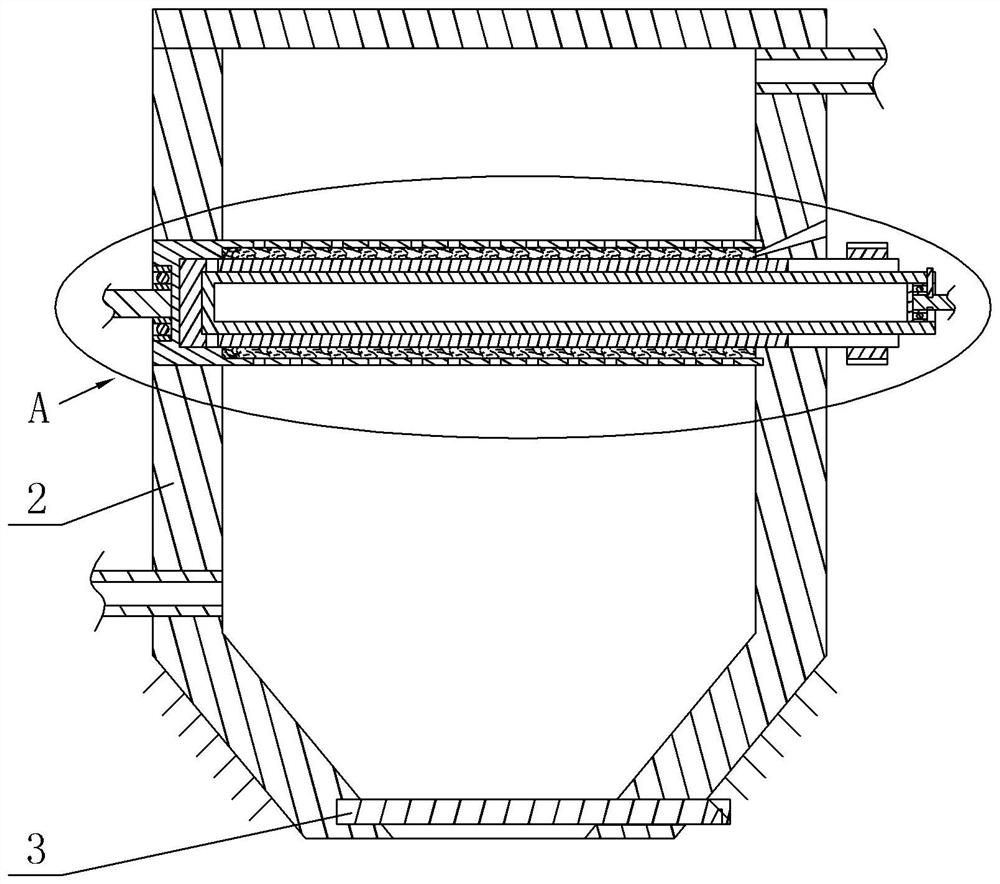
[0028] Step 2: If figure 1 , 2 As shown, the lower part of the denitrification tower 2 is fixedly installed on the frame by bolts, and the bottom of the denitrification tower 2 is provided with a leakage port, and the bottom of the denitrification tower 2 is slidably provided with a baffle 3 for sealing the leakage port; The upper part of the tower 2 is in the shape of a cuboid, and the rotating tube 4 is installed horizontally in the denitrification tower 2, such as figure 2 As shown, after the rotating pipe 4 pen...

Embodiment 2

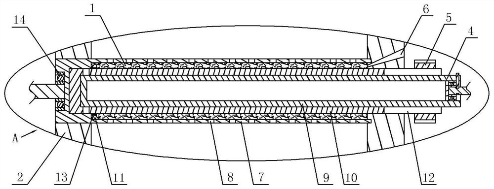
[0034] In order to solve the problem that there is no need to stop the kiln when replacing the denitrification cylinder 1, on the basis of embodiment 1, the denitrification tower 2 of embodiment 2 is also provided with a broken cylinder pouring mechanism. The broken cylinder pouring mechanism includes a broken cylinder unit and a pouring unit. In step 2 of Example 1, after the denitration cylinder 1 has been used for a period of time, the cylinder breaking unit can break the denitration cylinder 1 in the denitration tower 2, and the pouring unit can pour in the denitration tower 2 to form a new denitration cylinder 1.

[0035] Specifically, such as figure 2 As shown, the pouring unit includes a pouring port 6 and a casing 7, the left end of the casing 7 is sealed, the casing 7 runs through the left side wall of the denitrification tower 2 and is rotatably connected with the left side wall of the denitrification tower 2, and the left end of the casing 7 passes through the The ...


PUM

PropertyMeasurementUnit
particle sizeaaaaaaaaaa

Abstract

The invention belongs to the field of flue gas treatment, and specifically relates to a cement kiln flue gas denitrification process, comprising the following steps: step 1: pouring to form a denitrification cylinder, and forming pores on the wall of the denitrification cylinder; step 2: horizontally rotating the denitrification cylinder to set In the denitrification tower; Step 3: During the rotation of the denitrification cylinder, the flue gas enters the pores after contacting the denitrification cylinder, the vanadium and titanium in the slag act as a catalyst for the reduction of nitrogen oxides, and the biomass carbon powder oxidizes the nitrogen in the flue gas nitrogen oxides; step 4: In step 3, the flue gas entering the pores flows in the reverse direction under the barrier of the rotating tube, and the biomass carbon powder reduces the unreduced part of the nitrogen oxides in the flue gas to nitrogen, and reverses During the flow process, the denitrification cylinder continues to rotate with the rotating tube, and the nitrogen gas escapes from the pores and is discharged from the denitrification tower. When the technical solution is adopted, the denitrification effect of flue gas can be improved.

Description

technical field [0001] The invention belongs to the field of flue gas treatment, and in particular relates to a cement kiln flue gas denitrification process. Background technique [0002] A large amount of nitrogen oxides will be produced in the cement production process, and the direct discharge of nitrogen oxides in the flue gas will cause environmental pollution. At present, ammonia gas is injected into the denitrification tower, and ammonia gas is used as a reducing agent to reduce nitrogen oxides into nitrogen gas; however, the denitrification efficiency is low, and ammonia escape will occur, causing secondary pollution. [0003] Nowadays, carbonaceous material filter layers are usually installed in the denitrification tower. After nitrogen oxides pass through the carbonaceous material filter layer, the nitrogen oxides are reduced. The denitrification effect is not very good. Usually, it is necessary to install multiple carbonaceous material filter layers. The cost Hig...

Claims


Application Information

Patent Timeline
Patent Type & Authority Patents(China)
IPC IPC(8): B01D53/86B01D53/56
CPCB01D53/8631B01D2258/0233
Inventor 房浩李彬谷茂韩伟李明凯
Owner 冀东水泥重庆合川有限责任公司
Why Eureka
Try Eureka