Purification treatment method and purification treatment device for garbage incineration flue gas

A purification treatment and waste incineration technology, which is applied in the direction of gas treatment, chemical instruments and methods, combined devices, etc., can solve the problem of increasing the volume of SCR reactor, investment and catalyst consumption, affecting the total power generation and overall economic benefits of waste incineration plants, Problems such as high investment in heat exchangers and steam heaters, to achieve the effect of improving SCR denitrification efficiency, avoiding scale increase, and saving steam consumption

Pending Publication Date: 2019-12-31
中国环境保护集团有限公司
View PDF3 Cites 5 Cited by
  • Summary
  • Abstract
  • Description
  • Claims
  • Application Information

AI Technical Summary

Problems solved by technology

[0008] (1) Due to the need to arrange two-stage GGH and one-stage SGH, the investment in heat exchangers and steam heaters is high, and the floor area is large. At the same time, the cost of steam heating is high, which affects the total power generation and overall economic benefits of waste incineration plants. The disposal cost per ton of garbage will increase by about 20%;
[0009] (2) Since there are too many process links and the SCR reactor is arranged at the end of the process, with the increase of the process links, the injection of cooling water and the air leakage of the system gradually increase, resulting in the ratio of the total amount of flue gas processed at the end to The furnace outlet increased by about 50%, which led to a great increase in the volume, investment and catalyst consumption of the SCR reactor;
[0010] (3) Since the SCR reactor of this process is arranged at the end of the process, and the corresponding catalyst is also arranged at the end of the system, in order to reduce the steam consumption (for SGH), it is necessary to use a medium-low temperature catalyst with a temperature window of 200-300°C; The price of low-temperature catalyst is about 1.5-2 times that of medium-high temperature catalyst (temperature window 300-420°C), which increases the investment of the overall process;
[0011] (4) Compared with medium and high temperature catalysts (temperature window 300-420°C), the reaction activity and efficiency of medium and low temperature catalysts are lower, resulting in greater ammonia escape and polluting the environment
[0012] In addition, although the existing technology also has a process of arranging the SCR between the economizer and the air preheater to perform medium-high temperature denitration treatment on the flue gas, it is currently mainly used in the flue gas purification of coal-fired power plants
Since waste incineration flue gas contains a large amount of heavy metals that are different from those of coal-fired power plant flue gas, such as GeO 2 , Y 2 o 3 and Rb 2 O, etc., and about 20% of water vapor (the water content in the power plant flue gas is only 6-8%), which makes its treatment very difficult, and it is impossible to directly apply the high-temperature and high-dust arrangement SCR process method suitable for coal-fired power plants to Waste incineration flue gas treatment

Method used


Image

  • Purification treatment method and purification treatment device for garbage incineration flue gas
  • Purification treatment method and purification treatment device for garbage incineration flue gas
  • Purification treatment method and purification treatment device for garbage incineration flue gas

Examples


Embodiment 1

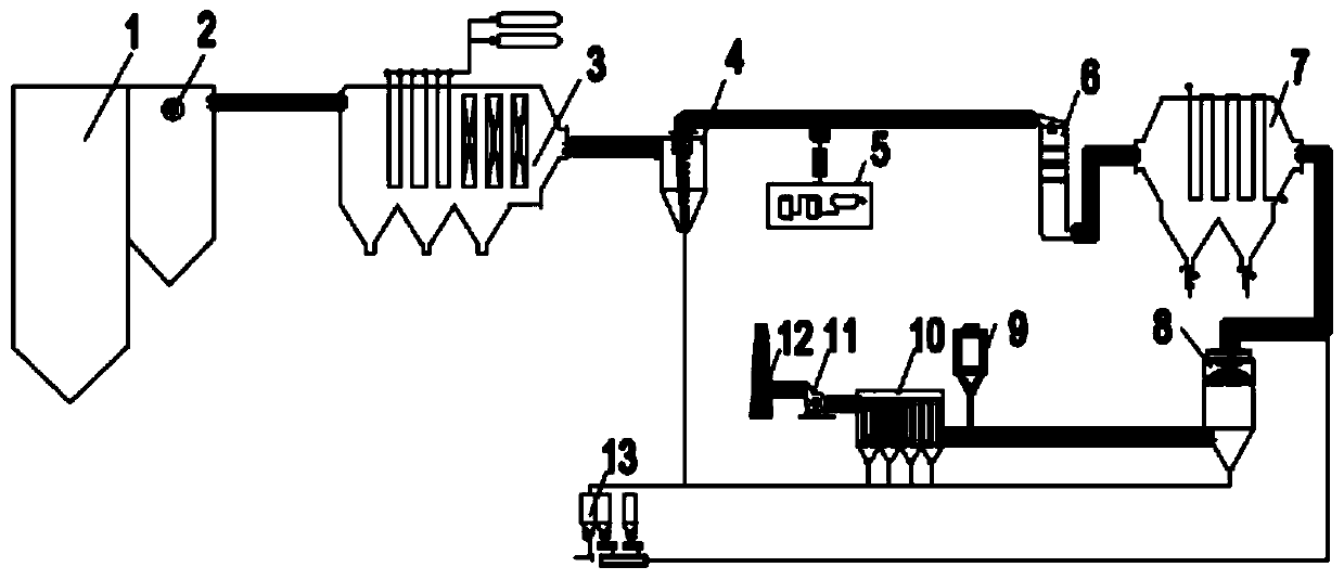
[0063]This embodiment provides a purification treatment device for waste incineration flue gas, including: an evaporator, a cyclone dust collector, an SCR system, an economizer, a semi-dry deacidification system, an activated carbon injection system, and a bag-type dust removal system connected in sequence.

[0064] Wherein, the SCR system includes: an SCR reactor; a denitrification reducing agent storage injection system, which is connected to the SCR reactor pipeline for supplying and injecting reducing agent; a soot cleaning and blowing system, which is connected to the SCR reactor pipeline connection, for cleaning the dust in the SCR reactor; and the SCR catalyst.

[0065] The denitration reductant storage and injection system includes: a reductant storage system and a reductant injection system; the reductant can be liquid ammonia, urea or ammonia water.

[0066] Wherein, when liquid ammonia is used as the reducing agent, the denitrification reducing agent storage and inj...

Embodiment 2

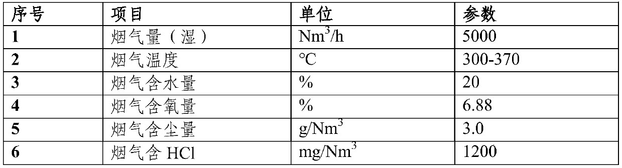
[0074] Taking a 400t / d waste incineration plant as an example, its flue gas composition is shown in Table 1.

[0075] Table 1

[0076]

[0077]

[0078] Adopt purification treatment device described in the present invention to carry out purification treatment, concrete steps are as follows:

[0079] (1) The flue gas is drawn from the evaporator at a flow rate of 13m / s, and the dust is removed by the cyclone dust collector, and the dust removal efficiency is 50%;

[0080] (2) The flue gas after dedusting enters the SCR system and is mixed with the reducing agent to carry out the SCR denitrification reaction;

[0081] Wherein, the reaction temperature of the SCR denitrification is 350°C;

[0082] The catalyst used for the SCR denitrification is the 18-hole garbage incineration flue gas denitrification special catalyst produced by CECEP Liuhe Tianrong (Shandong) Catalyst Company;

[0083] NH in the SCR denitrification process 3 with NO x The molar ratio is 1.2:1;

[0...


PUM

PropertyMeasurementUnit
Thicknessaaaaaaaaaa
Pore volumeaaaaaaaaaa
Apertureaaaaaaaaaa

Abstract

The invention belongs to the technical field of garbage incineration flue gas treatment and in particular relates to a purification treatment method and device for garbage incineration flue gas. The purification treatment method for garbage incineration flue gas comprises the following steps: leading out flue gas from an evaporator, performing treatment by using processes of cyclone dust collection-SCR (selective catalytic reduction) denitration-economizer-semidry method deacidification-activated carbon adsorption-bag type dust collection, and performing purification and emission. As SCR denitration is performed on the garbage incineration flue gas at a specific site (between the evaporator and an economizer), not only are investment and floor spaces of two stages of GGHs (gas-gas heaters)and one stage of an SGH (steam-gas heater) in a conventional purification treatment process reduced, but also the amount of vapor for heating the flue gas can be reduced; and in addition, the problems of SCR facility scale increase and investment increase can be avoided, the ammonia escape amount of the whole system can be reduced, and thus the process is energy-saving and environmentally friendly.

Description

technical field [0001] The invention belongs to the technical field of waste incineration flue gas treatment, and in particular relates to a purification treatment method and a purification treatment device for waste incineration flue gas. Background technique [0002] With the increasing output of municipal solid waste, the recycling, harmless and reduction of waste are becoming more and more important. Among many waste disposal methods such as landfill and composting, domestic waste incineration power generation can not only reduce the amount of waste, but also use the heat generated by waste incineration to generate electricity. It is an important domestic waste disposal method. [0003] The flue gas produced by domestic waste incineration contains a large amount of HF, HCl, SO 2 , NO x Such acid gases, dust, water vapor, dioxin, etc.; Among them, the dust contains iron oxide, thallium dioxide, aluminum oxide and other metals or heavy metal oxides, which is very difficu...

Claims


Application Information

Patent Timeline
IPC IPC(8): B01D53/75B01D53/56B01D53/60B01D53/68B01D53/06B01D50/00
CPCB01D53/75B01D53/56B01D53/60B01D53/68B01D53/06B01D2258/0291B01D2255/92B01D2255/9207B01D2257/2045B01D2257/2047B01D50/20
Inventor 周康魏民乐毛勇位郑朝晖黄智陈奕名黄明星洪战争黄佳松方艳利牛国平刘晓彤谢嘉瑞杨春凯李冬芳
Owner 中国环境保护集团有限公司
Why Eureka
Try Eureka