
Eureka
For R&D, Eureka makes reading and utilizing patents & technical documents easy.
Eureka AIR
Designed for self-driven R&D workflows. Generate viable solutions, solve complex R&D challenges, empower your innovation with AI.

Eureka Materials
Designed for material experts only. Revolutionize your material R&D, from search, analyze, to developing new materials.

TechResearch
Generate reliable direction feasibility study reports for your R&D in just a few steps.

TechSeek
Discover and master advanced knowledge NOW. Basics, ideas, possibilities, all at once.

TechMind
As an expert in R&D Theories, TechMind can generates customized viable solutions instantly.

TechRisk
Analyze your overall solution with one click, know your potential R&D risks in advance.

TechMonitor
Get weekly tech updates, stay abreast of the latest tech innovations and key insights.
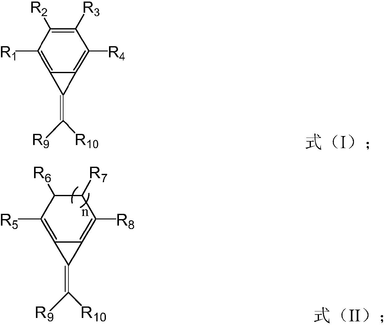
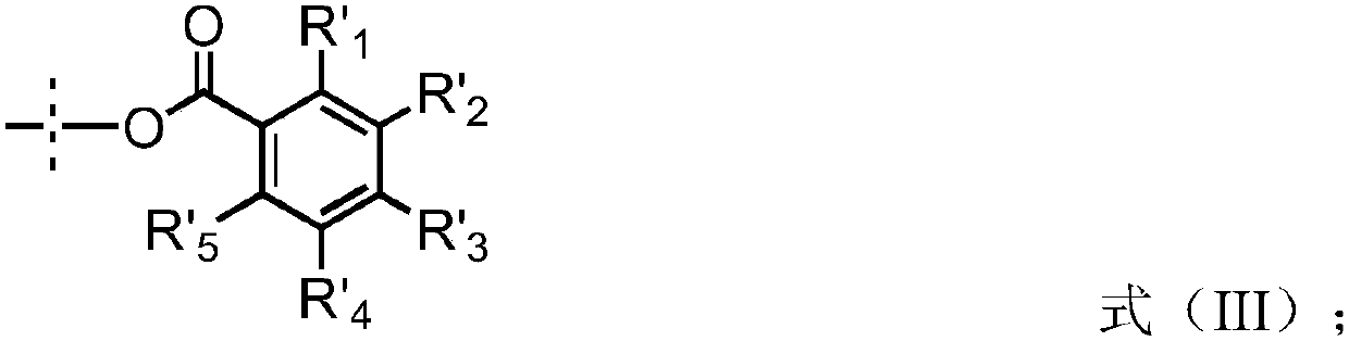
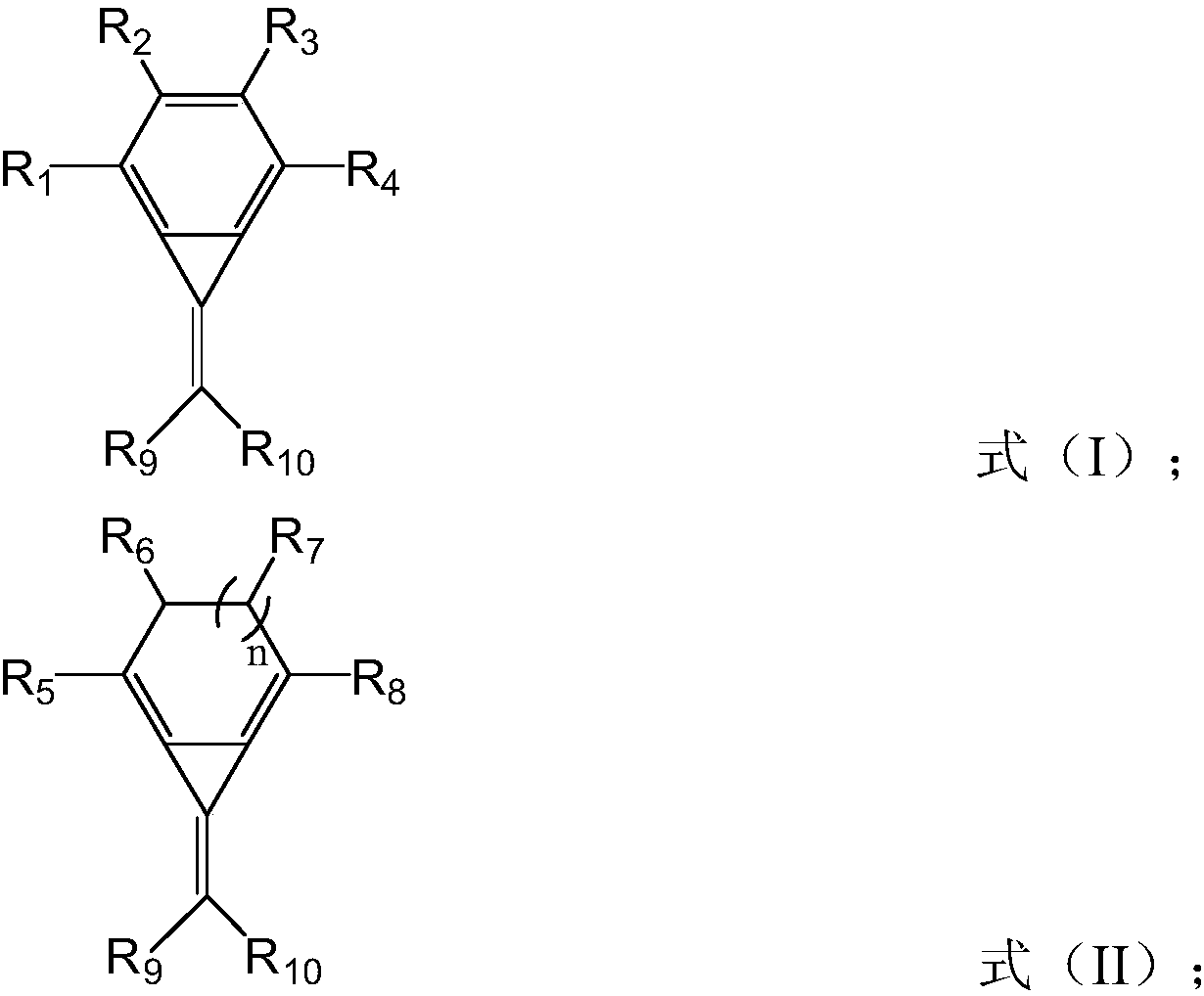
Hole injection material, hole injection layer comprising same, and OLED display panel
A technology of hole injection material and hole injection layer, which is applied in chemical instruments and methods, preparation of organic compounds, electrical components, etc., can solve problems such as hole injection performance needs to be improved, compound reduction potential is weak, etc., and achieve strong interaction effect, increase electrical conductivity, and good thermal stability
- Summary
- Abstract
- Description
- Claims
- Application Information
AI Technical Summary
Problems solved by technology
Method used
Image

Examples
preparation example 1
[0064] a compound A preparation method comprising the steps of:
[0065]
[0066] Potassium tert-butoxide (112.21mg, 1mmol), a-1 (306.09mg, 1mmol) and 10mLTHF were added to the reaction flask, and a-2 was generated after stirring at room temperature for 6 hours, and the product was directly used in the next step without purification Then add dioxomalononitrile (80mg, 1mmol) and stir for 1 hour, then add potassium fluoride (58.10mg, 1mmol) and tetrabutyllithium fluoride (261.46mg, 1mmol) and continue to stir for 1 hour; Reaction solution Concentrate and column to give a-3.
[0067] Characterization:
[0068] NMR: 13 H NMR: (1H, 73.1); (2H, 117.2); (2H, 118.4); (2H, 136.8); (2H, 143.9); (1H, 176.7);
[0069] Mass spectrum: 224 (molecular weight)
[0070] The LUMO energy level of the compound of Preparation Example 1 was 5.38 eV.
preparation example 2
[0072] a compound
[0073]
[0074] A preparation method comprising the steps of:
[0075]
[0076] Potassium tert-butoxide (112.21mg, 1mmol), a-1 (306.09mg, 1mmol) and 10mLTHF were added to the reaction flask, and a-2 was generated after stirring at room temperature for 6 hours, and the product was directly entered into the next step without purification . Add oxo(2,3,5,6-tetrafluoro-4-trifluoromethyl-phenyl)propionitrile (270.99 mg, 1 mmol) and stir for 1 hour, followed by potassium fluoride (58.10 mg, 1 mmol) and Tetrabutyllithium fluoride (261.46 mg, 1 mmol) was stirred for an additional 1 hour. The reaction solution was concentrated and passed through a column to obtain a-3.
[0077] Characterization:
[0078] NMR: 13 H NMR: (1H, 97.7); (1H, 102.7); (1H, 107.4); (1H, 115.4); (1H, 117.2); (1H, 118.4); (2H, 136.8); (1H, 97.7) ;(2H,118.4);(2H,143.0);(2H,143.9);(2H,144.3),(1H,151.5);
[0079] Mass spectrum: 414.99 (molecular weight).
[0080] The LUMO energy lev...
preparation example 3
[0082] a compound
[0083]
[0084] A preparation method comprising the steps of:
[0085]
[0086] Add c-1 (229.93mg, 1mmol) and 10mL cyclohexane to the reaction flask, then add n-butyllithium (32.03mg, 0.5mmol) dropwise to the reaction system to obtain intermediate c-2, and finally the reaction system continues Stir for 6 hours. The reaction solution was concentrated and passed through a column to obtain c-3.
[0087] Characterization:
[0088] NMR: 13 H NMR: (4H, 118.4); (2H, 132.3); (4H, 136.8); (4H, 143.9);
[0089] Mass spectrum: 319.99 (molecular weight).
[0090] The LUMO energy level of the compound of Preparation Example 3 was 5.20 eV.
PUM
 Abstract
Description
Claims
Application Information
 - R&D Engineer
- R&D Manager
- IP Professional
- Industry Leading Data Capabilities
- Powerful AI technology
- Patent DNA Extraction
Browse by: Latest US Patents, China's latest patents, Technical Efficacy Thesaurus, Application Domain, Technology Topic, Popular Technical Reports.
© 2024 PatSnap. All rights reserved.Legal|Privacy policy|Modern Slavery Act Transparency Statement|Sitemap|About US| Contact US: help@patsnap.com