Processing equipment for piezoelectric ceramic polymer composite material

A technology of composite materials and piezoelectric ceramics, applied in metal processing equipment, grinding/polishing equipment, piezoelectric/electrostrictive/magnetostrictive devices, etc., can solve problems such as uneven grinding, achieve good grinding effect, High grinding efficiency and uniform grinding effect

Active Publication Date: 2020-01-03
孙维涛
View PDF8 Cites 2 Cited by
  • Summary
  • Abstract
  • Description
  • Claims
  • Application Information

AI Technical Summary

Problems solved by technology

In the prior art, there is a problem of uneven grinding during the grinding process of the annular blank processed by the piezoelectric ceramic polymer composite material.

Method used


Image

  • Processing equipment for piezoelectric ceramic polymer composite material
  • Processing equipment for piezoelectric ceramic polymer composite material
  • Processing equipment for piezoelectric ceramic polymer composite material

Examples


Embodiment 1

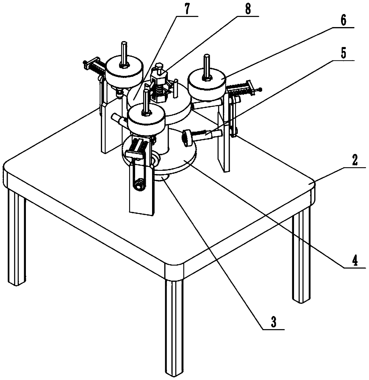
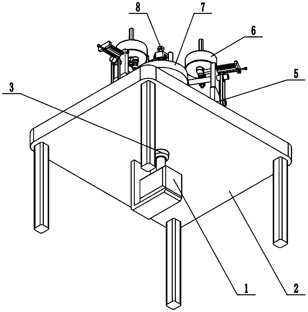
[0029] Such as Figure 1-9 As shown, a piezoelectric ceramic polymer composite material processing equipment includes a servo motor 1, a frame 2, a central shaft 3, a friction transmission disc 4, a speed change linkage part 5, a grinding part 6, a receiving disc 7 and an attachment part 8. The servo motor 1 is fixed on the frame 2 through the motor base; the servo motor 1 is connected to one end of the central shaft 3 through transmission; the central shaft 3 is connected to the frame 2 in rotation; the central shaft 3 is fixed The friction transmission disc 4 is connected; the friction transmission disc 4 is connected with three speed-change linkage parts 5; the three speed-change linkage parts 5 are evenly fixed on the frame 2; the three speed-change linkage parts 5 are respectively connected with a grinding part 6; The three grinding parts 6 are respectively fixed on the three speed-changing linkage parts 5; the other end of the central shaft 3 is fixedly connected to the ...

Embodiment 2

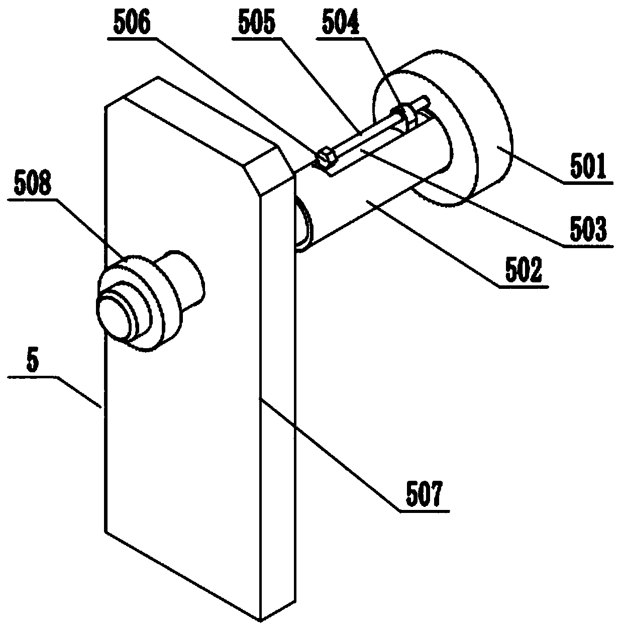
[0031] Such as Figure 1-9As shown, the speed change linkage part 5 includes a friction linkage wheel 501, a rotating tube 502, a rotating shaft 503, a slider 504, a speed change adjustment screw 505, an adjustment turn block 506, a lower shelf plate 507 and a first pulley 508; The transmission disc 4 is vertically frictionally connected to the friction linkage wheel 501; the friction linkage wheel 501 is fixed on the rotating tube 502; the rotating shaft 503 is slidably fitted in the rotating tube 502; a slider 504 is fixedly connected to the rotating shaft 503, The block 504 is slidably fitted in the chute of the rotating tube 502; the middle part of the variable speed adjusting screw 505 is connected to the slide block 504 by threads, and one end of the variable speed adjusting screw 505 is rotatably fitted on the friction linkage wheel 501, and the middle part of the variable speed adjusting screw 505 The other end is affixed with an adjustment rotary block 506; the rotati...

Embodiment 3

[0033] Such as Figure 1-9 As shown, the grinding part 6 includes a second pulley 601, a worm 602, an upper shelf plate 603, a locking bolt 604 and a grinding mechanism 605; the first pulley 508 is connected to the second pulley 601 through a synchronous belt drive; The second pulley 601 is fixed on one end of the worm screw 602, and the worm screw 602 is rotated and fitted on the upper shelf plate 603, and the upper shelf plate 603 is fixed on the lower shelf plate 507; the other end of the worm screw 602 is connected to the grinding mechanism 605 by transmission; Slidingly connected on the upper shelf plate 603; the locking bolt 604 is screwed on the upper shelf plate 603, and the inner side of the locking bolt 604 is pressed against the grinding mechanism 605. When the first pulley 508 rotates, it can drive the second pulley 601 to rotate through the synchronous belt. When the second pulley 601 rotates, it can drive the worm 602 to rotate. When the worm 602 rotates, it can ...


PUM


Abstract

The invention relates to the field of processing of piezoelectric ceramic polymer composite materials, in particular to processing equipment for a piezoelectric ceramic polymer composite material. Theprocessing equipment comprises a servo motor, a rack, a central shaft, a friction transmission disc, variable speed linkage parts, grinding parts, a bearing disc and a joint part. The servo motor isfixed to the rack through a motor base. The servo motor is in transmission connection with one end of the central shaft. The center shaft is rotationally connected to the rack. The friction transmission disc is fixedly connected to the central shaft. The friction transmission disc is in transmission connection with the three variable speed linkage parts. The three variable speed linkage parts areuniformly fixed to the rack in a surrounding manner. The three variable speed linkage parts each are in transmission connection with one grinding part. The three polishing parts are correspondingly fixed to the three variable speed linkage parts. The other end of the central shaft is fixedly connected with the bearing disc. The joint part is fixed to the middle of the bearing disc. By the adoptionof the processing equipment, a circular ring blank processed by the piezoelectric ceramic polymer composite material can be uniformly ground, and the grinding effect is good.

Description

technical field [0001] The invention relates to the field of processing piezoelectric ceramic polymer composite materials, in particular to processing equipment for piezoelectric ceramic polymer composite materials. Background technique [0002] Piezoelectric ceramics refer to the ferroelectric ceramics which are formed by mixing oxides (zirconia, lead oxide, titanium oxide, etc.) at high temperature and sintered at high temperature and reacted in the solid state, and through direct current high-voltage polarization treatment to make them have piezoelectric effect. The general term for ceramics is a functional ceramic material that can convert mechanical energy and electrical energy into each other. Due to its good mechanical properties and stable piezoelectric properties, piezoelectric ceramics, as an important functional material sensitive to force, heat, electricity and light, have been used in sensors, ultrasonic transducers, micro-displacers and other electronic compone...

Claims


Application Information

Patent Timeline
Patent Type & Authority Applications(China)
IPC IPC(8): B24B19/00B24B19/11B24B27/00B24B41/06B24B47/12B24B47/20B24B47/22H01L41/337
CPCB24B19/008B24B19/11B24B27/0076B24B41/067B24B47/22B24B47/12B24B47/20H10N30/086
Inventor 孙维涛
Owner 孙维涛
Why Eureka
Try Eureka