Burning lance and energy-saving and environment-friendly kiln

An energy-saving and environmentally friendly kiln technology, applied in furnaces, burners, combustion methods, etc., can solve the problems of high energy consumption and low utilization rate of waste heat in kilns, achieve full combustion, fast combustion reaction speed, and reduce cross-sectional temperature difference Effect

Pending Publication Date: 2020-01-07
山东狮王陶瓷有限公司
View PDF0 Cites 0 Cited by
  • Summary
  • Abstract
  • Description
  • Claims
  • Application Information

AI Technical Summary

Problems solved by technology

[0003] In order to solve the problems of high energy consumption and low waste heat utilization rate of kilns in the prior art, the present invention provides a burner and an energy-saving and environmentally friendly kiln. The burner controls the gas hole and the combustion air hole, and the combustion is sufficient And the speed is fast, which can reduce the energy consumption of the kiln; the energy-saving and environmentally friendly kiln uses the burner, and a combustion-supporting air heating heat exchange pipe is added in the slow cooling section, so that the waste heat of the kiln is fully utilized. After heating the heat exchange pipes, the heating combustion-supporting air is preheated, which reduces the consumption of fuel and thus achieves the effect of energy saving

Method used


Image

  • Burning lance and energy-saving and environment-friendly kiln
  • Burning lance and energy-saving and environment-friendly kiln
  • Burning lance and energy-saving and environment-friendly kiln

Examples


Embodiment 1

[0029] The burner is one of the core components of the kiln, which determines the quality of ceramic products such as brick shape and color. In order to find a spray gun compatible with natural gas, the applicant has always focused on the continuous research and development of the equipment, and developed a new and efficient natural gas energy-saving burner. This embodiment provides a burner, which uses gas as a raw material, and through reasonable control of the gas holes and the combustion-supporting air holes, the combustion is complete and fast, and the energy consumption of the kiln can be reduced.

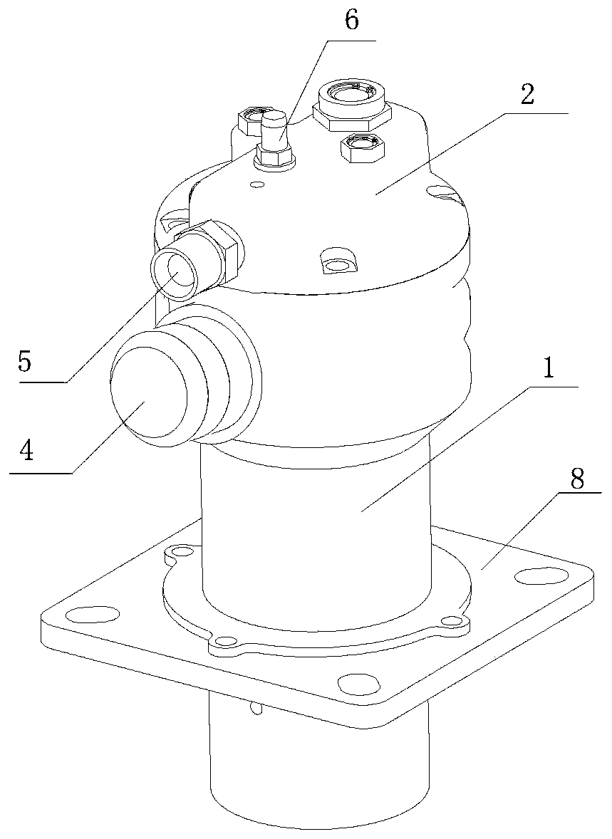
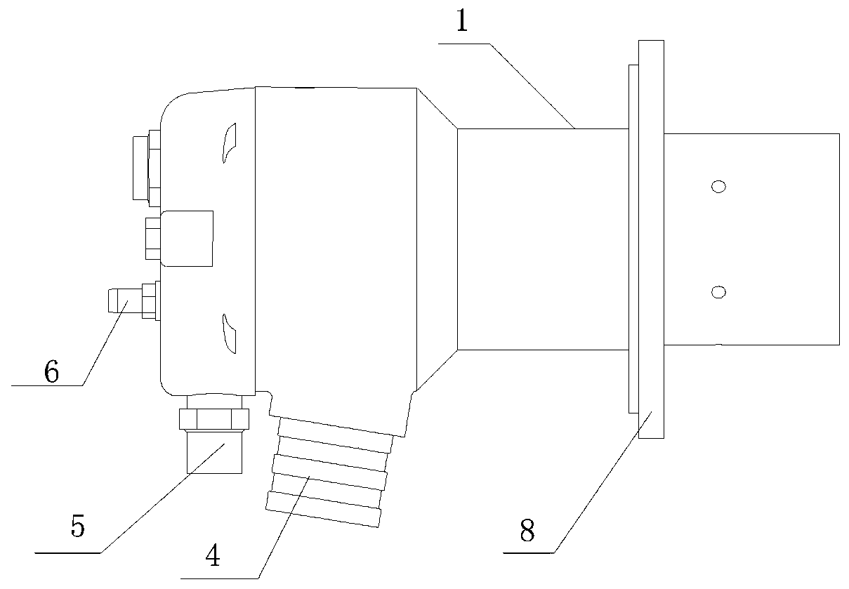
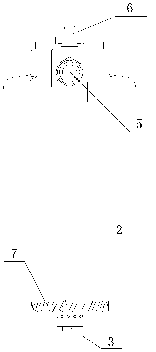
[0030] refer to Figure 1-Figure 4 , the burner includes a holster 1, a gun core 2 and a gun head 3, the holster 1 is fixedly set on the outside of the gun core 2, the holster 1 is provided with a combustion-supporting air inlet 4, the inner wall of the holster 1 and the gun core A combustion air cavity is formed between the outer walls of 2. One end of the gun core 2 is pr...

Embodiment 2

[0034] In order to solve the problems of high energy consumption and low waste heat utilization rate of the kiln in the prior art, this embodiment provides an energy-saving and environment-friendly kiln. Reasonable control of the combustion-supporting air hole, so that the combustion is sufficient and fast, can reduce the energy consumption of the kiln; and the energy-saving and environmentally friendly kiln is equipped with a combustion-supporting air heating heat exchange pipe in the slow cooling section, so that the waste heat of the kiln is obtained. Fully utilized, after the heat exchange pipe is heated by the combustion-supporting air, the heating combustion-supporting air is preheated, reducing the consumption of fuel, thereby achieving the effect of energy saving.

[0035] Specifically, the energy-saving and environmentally friendly kiln includes a kiln body, a burner, a fuel tank, and a combustion fan. The kiln body includes a preheating section, a high temperature sec...

Embodiment 3

[0043] Different from the above-mentioned embodiments, the energy-saving and environment-friendly kiln also includes a heat exchanger, and the top of the slow cooling section is provided with a combustion-supporting air heating heat exchange tube, and the combustion-supporting air heating heat exchange tube is connected to the inlet end of the heat exchanger for heat exchange. The outlet end of the device is connected with the inlet of the combustion-supporting fan through the combustion-supporting pipe. At present, most of the combustion-supporting air used in the kiln is natural air. When the air at normal temperature is sent into the kiln, it will absorb a considerable part of the heat, which often results in waste of heat.

[0044] The combustion-supporting air heating heat exchange tubes in this embodiment are arranged in multiples, and are evenly distributed on the top of the slow cooling section. The diameter of each combustion-supporting air heating heat exchange tube i...


PUM

PropertyMeasurementUnit
Diameteraaaaaaaaaa

Abstract

The invention specifically relates to a burning lance and an energy-saving and environment-friendly kiln. The burning lance comprises a lance sleeve, a lance core and a lance head. The lance sleeve isarranged on the outer side of the lance core in a sleeving manner. The lance core and the lance head are fixedly connected. A wind blocking sheet is fixed to the portion, close to the lance head, ofthe outer wall of the lance core. Combustion-supporting air holes are formed in the wind blocking sheet. Fuel gas holes are further formed in the portion, close to the lance head, of the side wall ofthe lance core and are located between the lance head and the wind blocking sheet. The burning lance is high in combustion reaction speed and sufficient in combustion, and the energy consumption is reduced. The energy-saving and environment-friendly kiln comprises a kiln body, burning lances, a fuel tank, a heat exchanger and a combustion-supporting draught fan; the burning lances penetrate through the side wall of a high-temperature section of the kiln body; fuel gas inlets are connected with the fuel tank; combustion-supporting air inlets are connected with an outlet of the combustion-supporting draught fan; combustion-supporting air heating and heat exchanging pipes are arranged on the top of a slow-cooling section of the kiln body and are connected with the inlet end of the heat exchanger; and the outlet end of the heat exchanger is connected with an inlet of the combustion-supporting draught fan. Waste heat of the energy-saving and environment-friendly kiln is sufficiently utilized, and the use amount of fuel is decreased.

Description

technical field [0001] The invention belongs to the technical field of ceramic firing equipment, and in particular relates to a burner and an energy-saving and environment-friendly kiln. Background technique [0002] Ceramic bricks are plate-shaped or block-shaped ceramic products produced by molding and sintering processes from clay and other inorganic non-metallic raw materials. They are used to decorate and protect walls and floors of buildings and structures. They are usually dried at room temperature. Pressing, extruding or other molding methods, then drying and firing at a certain temperature, ceramic tiles have attracted more and more attention because of their beauty, safety and durability, and the demand has also increased. In the process of drying and firing ceramic bricks, a kiln is required, while the traditional kiln requires a large amount of firing materials, which is a high energy consumption process, and the utilization rate of waste heat is low, and the rat...

Claims


Application Information

Patent Timeline
IPC IPC(8): F23D14/00F23D14/46F23D14/60F23D14/66F27B17/00F27D17/00
CPCF23D14/00F23D14/46F23D14/60F23D14/66F27B17/0041F27D17/004F27D99/0033F27D2099/0056Y02E20/34
Inventor 袁辉恺胡立亮
Owner 山东狮王陶瓷有限公司
Why Eureka
Try Eureka