
Electromagnetic pulse radiation field test probe, test system and test method

An electromagnetic pulse and radiation field technology, applied in the field of electromagnetic pulse radiation field test probes, can solve the problems of antenna field distortion, complex circuit structure, signal distortion, etc., and achieve the effects of wide operating frequency range, simple circuit structure, and adjustable sensitivity

Pending Publication Date: 2020-01-10
ARMY ENG UNIV OF PLA
View PDF0 Cites 9 Cited by
  • Summary
  • Abstract
  • Description
  • Claims
  • Application Information

AI Technical Summary

Problems solved by technology

Since the frequency range covered by the antenna itself is limited, signal distortion will inevitably occur in the ultra-wideband electromagnetic pulse test, and the field waveform cannot be truly restored, and larger-sized antennas will also produce field distortion effects; in addition, using Coaxial cable for signal transmission will cause itself to be affected by strong electromagnetic pulse field, thus introducing external electromagnetic interference
Therefore, the existing electromagnetic pulse radiation field test devices all use optical fiber as the carrier of signal transmission, which involves the modulation of electrical and optical signals. The core technical problem is to realize the acquisition and conversion of electric field signals in an ultra-wide frequency band. and modulation, and finally realize the undistorted test of the electromagnetic pulse radiation field. The previous research mainly used the electric small antenna to sense the electric field signal, and then realized the optical signal by the impedance transformation circuit, follower circuit, constant current circuit or amplification drive circuit and electro-optic conversion circuit. Output, due to the complex circuit structure, especially the impedance transformation circuit and the amplification drive circuit will seriously limit the signal transmission bandwidth, resulting in the loss of high frequency components

Method used


Image

  • Electromagnetic pulse radiation field test probe, test system and test method
  • Electromagnetic pulse radiation field test probe, test system and test method
  • Electromagnetic pulse radiation field test probe, test system and test method

Examples


Embodiment Construction

[0023] The following describes the technical solutions in the embodiments of the present invention clearly and completely with reference to the accompanying drawings in the embodiments of the present invention. Obviously, the described embodiments are only a part of the embodiments of the present invention, rather than all the embodiments. Based on the embodiments of the present invention, all other embodiments obtained by those of ordinary skill in the art without creative work shall fall within the protection scope of the present invention.

[0024] In the following description, many specific details are explained in order to fully understand the present invention, but the present invention can also be implemented in other ways different from those described here, and those skilled in the art can do it without departing from the connotation of the present invention. Similar promotion, therefore, the present invention is not limited by the specific embodiments disclosed below.

[...


PUM


Abstract

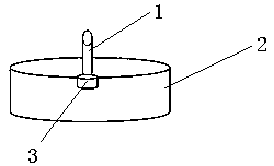
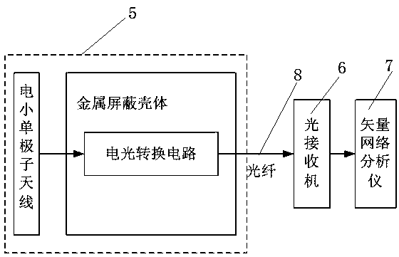
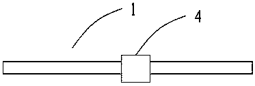
The invention discloses an electromagnetic pulse radiation field test probe, a test system and a test method. The probe comprises an electrically small monopole antenna, a metal shielding shell and anelectro-optical conversion circuit; one end of the electrically small monopole antenna is positioned outside the metal shielding shell; the other end of the electrically small monopole antenna penetrates through an antenna lead-in hole in the metal shielding shell and then enters the metal shielding shell; and the end part of the electrically small monopole antenna entering the metal shielding shell is electrically connected with the signal input end of the electro-optical conversion circuit; and the signal output end of the electro-optical conversion circuit is the optical signal output endof the test probe. The probe has the advantages of wide working frequency range, large dynamic range, adjustable sensitivity, simple circuit structure, easiness in miniaturization and the like.

Description

Technical field [0001] The invention relates to the technical field of electromagnetic signal detection, in particular to an electromagnetic pulse radiation field test probe, a test system and a test method. Background technique [0002] Electromagnetic pulse has the characteristics of fast rising edge, high amplitude, and narrow pulse width in the time domain. In the frequency domain, it covers a wide frequency band, which makes various electronic devices susceptible to electromagnetic pulses. Therefore, the study of electromagnetic pulse has become particularly important for the electromagnetic compatibility test of electronic equipment. In the test, lightning electromagnetic pulse, electrostatic electromagnetic pulse, nuclear electromagnetic pulse and ultra-wideband electromagnetic pulse are often used as electromagnetic pulse sources, using field forming devices The electromagnetic pulse field is radiated. By analyzing the time-domain waveform of the electromagnetic pulse rad...

Claims


Application Information

Patent Timeline
Patent Type & Authority Applications(China)
IPC IPC(8): G01R29/08
CPCG01R29/0814G01R29/0885
Inventor 赵敏陈亚洲程二威周星杨清熙王妍
Owner ARMY ENG UNIV OF PLA
Learn More