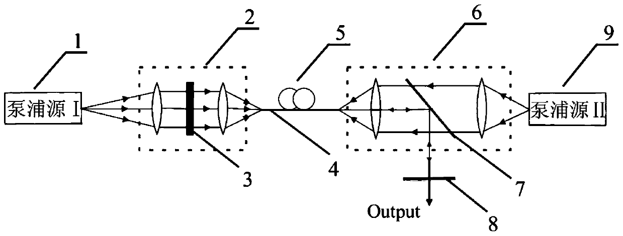
[0045] The present invention will be further described below in conjunction with accompanying drawing:
[0046] like figure 2 as shown,
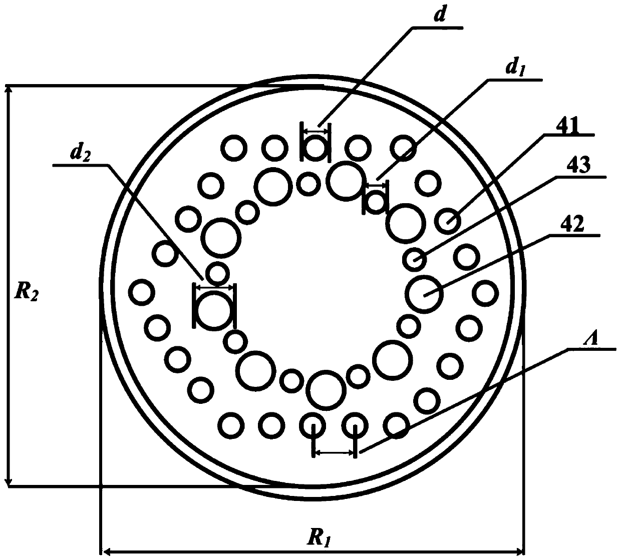
[0047] A large mode field photonic crystal fiber 4 based on a fiber laser, including a perfect matching layer, a core layer and a cladding layer, the cladding layer is placed outside the fiber core layer, and the perfect matching layer is placed outside the cladding layer; the cladding layer includes a regular hexagonal period A plurality of air holes I41 with a diameter d in a permanent arrangement;
[0048] The core layer includes nine regular nonagonal periodic arrays whose diameters are all d 2 The air hole II 42, nine diameters are d 1 The air hole III 43;
[0049] Air holes II42 and air holes III43 are distributed at intervals;
[0050] Nine air holes II 42 are respectively placed at nine endpoints of the regular nonagon;
[0051] Nine air holes III 43 are placed at the midpoints of the nine sides of the regular nonagon respectively;
[0052] The diameter d of the air hole I41 is 1-5μm; the diameter of the air hole II42 is d 2 9-13μm; air hole Ⅲ43 diameter d 1 3-7μm; cladding air hole spacing Λ is 13-17μm.
[0053] Preferably, the diameter d of the air hole I41 is 3 μm; the diameter d of the air hole II42 is 2 11μm; air hole Ⅲ43 diameter d 1 is 5μm; cladding air hole spacing Λ is 15μm.
[0054] Preferably, the background material of photonic crystal fiber 4 is SiO 2.
[0055] The optical fiber amplifier has a photonic crystal fiber 4 as an optical amplification medium.
[0056] A fiber laser with a photonic crystal fiber 4 as an optical amplification medium.
[0057] like figure 2 as shown,
[0058] The outermost ring represents the PCF Perfect Matched Layer (PerfectMatchedLayers, PML) absorption boundary condition, and the near-core region introduces nine large air holes II and nine small air holes III, forming a regular nonagonal periodic structure. where R 1 is the radius of PCF, R 2 is the outer diameter of the perfect isolation layer, Λ is the air hole spacing in the cladding, d is the diameter of the air holes arranged periodically in the cladding, d 1 and d 2 are the diameters of large air holes and small air holes in the core area, respectively, the refractive index of air is 1, and the background material SiO 2 The refractive index is 1.45.
[0059] The calculation and analysis results show that the mode field area is greatly affected by the spacing of the cladding air holes (between the air holes I), the diameter of the air hole I plays a leading role in the nonlinear optimization, and the limiting loss mainly depends on the inner air holes (air hole II, air hole III) diameter and cladding air hole spacing. The air hole structure proposed in this application is a circular structure, which is beneficial to the process. Based on the comprehensive consideration of the limited loss, nonlinear effect, and effective mode field area, the optimal structural parameters of the PCF are selected as the diameter d of the air hole I is 3 μm, and the air hole Ⅱ diameter d 1 11μm, air hole Ⅲ diameter d 2 5 μm, cladding air hole spacing is 15 μm.
[0060] The limiting loss varies with wavelength as image 3 As shown, it can be seen that the confinement loss is always less than 10 in the range of wavelength variation from 0.84μm to 1.6μm -6 dB·m -1 , and at a wavelength of 1.064μm, its limiting loss can be as low as 4.55×10 -7 dB·m -1 , and the variation of the limiting loss remains relatively flat over the entire wavelength sweep.
[0061] Figure 4 The relationship between the effective mode field area and the nonlinear coefficient of the PCF after the optimized design of this application is given. It can be seen that the mode field area and the nonlinear coefficient show an obvious inverse proportional relationship. At a wavelength of 1.064 μm, the effective mode field area of the PCF of this application can be as high as 3118.4 μm 2 , and its corresponding nonlinear coefficient can be as low as 5.68×10 -5 m -1 ·W -1 , showing the excellent characteristics of large mode field area and low nonlinear effect. The figure shows the nonlinear coefficient γ91; the effective mode field area A eff 92;
[0062] Figure 5 The distribution of the fundamental mode transverse electric field component obtained by COMSOL simulation is given. It can be seen that the LMA-PCF fundamental mode electric field mode of this application is more concentrated in the core area, which is conducive to realizing a large mode field area. Figure 5 Shown in the strong energy zone 11; weak energy zone 12, the weak energy zone 12 to the strong energy zone 11 is the state of gradually increasing energy.
[0063] Image 6 The distribution of the three-dimensional energy potential field obtained by COMSOL simulation is given. It can be seen that the energy in the core region of the fundamental mode of the LMA-PCF designed in this application is stronger than that of the ordinary PCF. And in the case that the effective mode refractive index of the core region is initially set to 1.45, the effective mode refractive index of the LMA-PCF designed in this application is 1.449603472, which is very close. According to the PCF normalized frequency theoretical formula, the normalized frequency of the optical fiber varies irregularly with the wavelength, but is always less than Π, which ensures the single-mode transmission of the LMA-PCF. Image 6 Shown in the strong energy zone 11; weak energy zone 12, the weak energy zone 12 to the strong energy zone 11 is the state of gradually increasing energy.
[0064] Key points of this application: large mode field area, low confinement loss, low nonlinear coefficient, strong stability, small unit size, easy integration and process processing.
[0065] The point to be protected: the photonic crystal fiber structure with a regular nonagonal core area and a regular hexagonal cladding area.
[0066] Comparative analysis: This patent studies the transmission characteristics of photonic crystal fiber through the equivalent refractive index method, and proposes a technical solution that can optimize the large mode field area of the fiber, using the finite difference time domain method (FiniteDifferenceTimeDomain; FDTD) combined with the PML boundary The effective mode field area was calculated under conditions, and the performance indicators such as fiber nonlinear coefficient and limited loss were further optimized by multi-stage method, and a new type of passive single-mode large-mode field low-loss photonic crystal fiber was designed. The fiber performance comparison table between the traditional optical fiber and the new large-mode field photonic crystal fiber designed by this patent is as follows:
[0067]
[0068] It can be seen from Table 1 that in order to meet higher power and higher beam quality laser output, the optimized fiber laser solution proposed in this patent is obviously superior to the traditional technology.
[0069] The basic principles, main features and advantages of the present invention have been shown and described above. Those skilled in the industry should understand that the present invention is not limited by the above-mentioned embodiments. What are described in the above-mentioned embodiments and the description only illustrate the principle of the present invention. Without departing from the spirit and scope of the present invention, the present invention will also have Variations and improvements are possible, which fall within the scope of the claimed invention. The protection scope of the present invention is defined by the appended claims and their effects.