Tower biological filter with fast surface renewal
A biological filter and tower type technology, applied in the field of industrial wastewater treatment devices, can solve the problems of packing blockage, shortening equipment operation cycle, thick packing layer, etc., and achieve the effect of accelerating stripping, avoiding wall flow effect, and shortening the time
- Summary
- Abstract
- Description
- Claims
- Application Information
AI Technical Summary
Problems solved by technology
Method used
Image
Examples
Embodiment 1
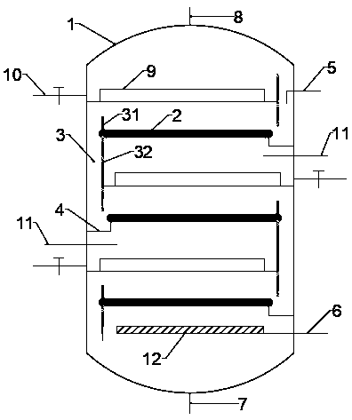
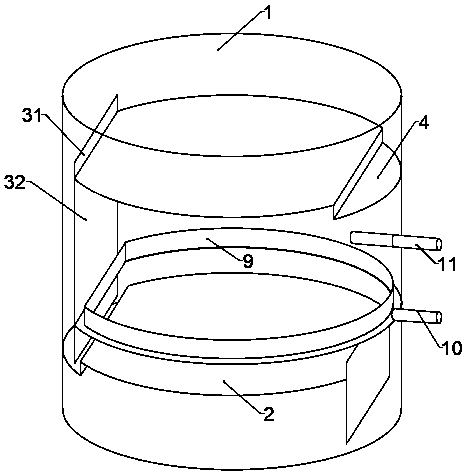
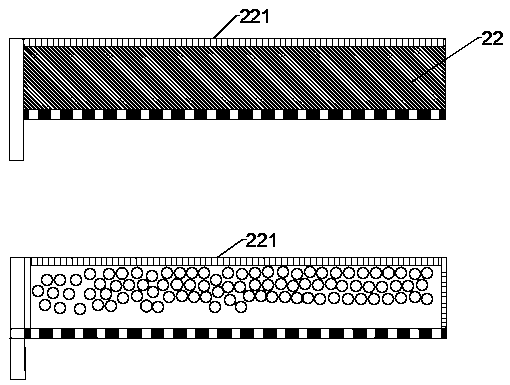
[0028] A tower-type biological filter with rapid surface renewal, including a tower body 1, a sewage inlet 5 and an exhaust port 8 arranged on the top of the tower body 1, and a water outlet 7 and an air inlet 6 at the bottom of the tower body 1 , the inner interval of the tower body 1 is provided with several layers of trays 2, the trays 2 are sieve trays, and the upstream and downstream of each tray 2 are respectively equipped with a liquid receiving tray 4 and a downcomer 3; The downcomer 3 is formed by an overflow weir 31 located on the upper surface of the tray 2, a downcomer wall 32 located on the lower surface of the tray 2 and the inner wall of the tower body 1; A packing layer 22 is arranged on it; the height of the packing layer 22 does not exceed the overflow weir 31; the packing layer 22 includes a limiting element 221, and the limiting element 221 is surrounded by the tray 2 and the overflow weir 31 The packing bin where the packing is placed; the limiting element...
Embodiment 2
[0031] The difference from Example 1 is that the tray 2 is a valve tray, and several float valves 21 are arranged on the valve tray. The valve surface of the float valve 21 includes a sieve hole 212 in the middle and The valve edge 211 on the edge of the valve surface; the float valve 21 also includes two opposite valve legs 213 and a valve foot 216 at the bottom of the valve legs 213, and the valve foot 216 is allowed to be bent during installation; The corresponding sides of the two valve legs 213 are connected by a grid plate 215, and several grid holes 214 are arranged on the grid plate 215; The widths are all smaller than the smallest dimension of the granular filler.
Embodiment 3
[0033] The difference from Embodiment 2 is that the float valve 21 is a guide float valve, and the guide float valve is provided with a guide hole 217 at the middle and lower part of the valve leg 213 on one side, and the guide hole 217 is only exposed when the gas phase is strongly impacted. The upper surface of the tray 2; two kinds of float valves 21 of type A and type B are arranged on the tray 2, and the guide hole 217 of the type A float valve 21 is located on the valve leg 213 on the downstream side thereof; The guide hole 217 of the float valve 21 is located on the valve leg 213 on the upstream side thereof. The A-type and B-type float valves 21 are arranged in rows at intervals.
PUM
 Abstract
Description
Claims
Application Information
 - R&D
- Intellectual Property
- Life Sciences
- Materials
- Tech Scout
- Unparalleled Data Quality
- Higher Quality Content
- 60% Fewer Hallucinations
Browse by: Latest US Patents, China's latest patents, Technical Efficacy Thesaurus, Application Domain, Technology Topic, Popular Technical Reports.
© 2025 PatSnap. All rights reserved.Legal|Privacy policy|Modern Slavery Act Transparency Statement|Sitemap|About US| Contact US: help@patsnap.com


