Vortex type micro-pump

A micro-pump and vortex technology, applied in non-variable-capacity pumps, pumps, pump components, etc., can solve the problems of low head of the micro-pump, large size of the micro-pump, low hydraulic efficiency, etc., to improve the rated driving force and space utilization. High rate and the effect of improving working power

Pending Publication Date: 2020-01-17
HUAWEI DEVICE CO LTD
View PDF0 Cites 3 Cited by
  • Summary
  • Abstract
  • Description
  • Claims
  • Application Information

AI Technical Summary

Problems solved by technology

As the core driving component of the liquid cooling system, the micropump drives the working fluid to circulate continuously in the liquid cooling system. However, due to its complex structure and moving parts, it is the bottleneck of the miniaturization and thinning of the liquid cooling system.
At present, most of the micropumps whose hydraulic performance meets the head requirements of the liquid cooling system are large in size, which cannot meet the thickness requirements of portable electronic devices (such as laptops, mobile phones, etc.) for micropumps, and the existing thin micropumps are limited by thickness , the design method is immature, and there are mainly the following problems:
[0004] 1. The small size of the impeller leads to a low head that the micropump can provide; 2. The design of the impeller and the pump chamber is rough, and the design of the pump chamber does not match the impeller, so that the work done by the impeller to the fluid has more losses inside the micropump , the hydraulic efficiency is low; 3. The size of the motor is small, and the motor type mostly adopts the inner rotor type, and the rated driving force is insufficient. As a result, when the micro pump is working, the motor is in an overload state and the efficiency is extremely low

Method used


Image

  • Vortex type micro-pump
  • Vortex type micro-pump
  • Vortex type micro-pump

Examples


Embodiment Construction

[0032] In order to make the object, technical solution and advantages of the present invention clearer, the present invention will be further described in detail below in conjunction with the accompanying drawings and embodiments. It should be understood that the specific embodiments described here are only used to explain the present invention, not to limit the present invention. In addition, the technical features involved in the various embodiments of the present invention described below can be combined with each other as long as they do not constitute a conflict with each other.

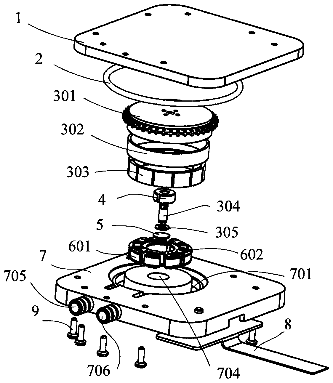
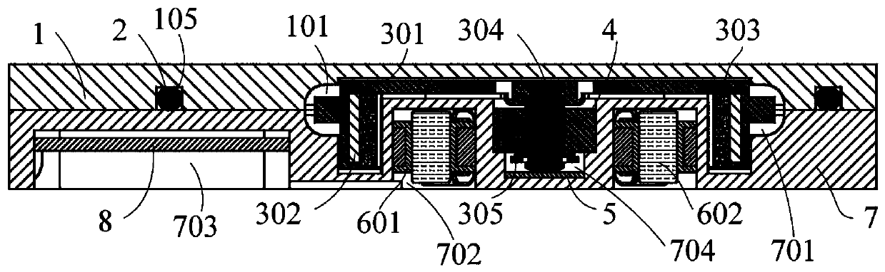
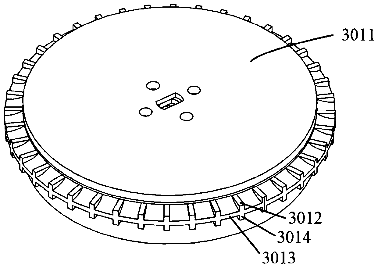
[0033] see figure 1, figure 2 and Figure 9 , the vortex micropump provided by the preferred embodiment of the present invention, the micropump includes a volute 1, a seal 2, a rotor assembly 3, a bearing 4, a wear plate 5, a stator assembly 6, a base 7, a controller 8 and A plurality of screws 9 , the seal 2 is arranged in the volute 1 , and it is located between the volute 1 and the base 7...


PUM


Abstract

The invention belongs to the related technical field of micro-pumps, and discloses a vortex type micro-pump. The micro-pump comprises a volute, a rotor component, a stator component and a base; the volute is connected to the base; a pump cavity is formed by the volute and the base together; the rotor component is accommodated in the pump cavity and is rotationally connected to the base; the statorcomponent is arranged in the base; the outer side of the stator component is sleeved with the rotor component; the rotor component comprises a columnar impeller; the impeller is rotationally connected to the base and comprises an impeller base body, multiple upper blades, multiple lower blades and an annular blade separator; the blade separator is arranged on the outer circumference of the impeller base body; and the upper blades and the lower blades are arranged on the blade separator respectively and are located on two opposite sides of the blade separator respectively. According to the micro-pump, the lift and the efficiency are increased, and the micro-pump is relatively high in applicability and compact in structure.

Description

technical field [0001] The invention belongs to the technical field related to micropumps, and more specifically relates to a vortex micropump. Background technique [0002] A pump is a machine that transports fluids or pressurizes fluids, and is widely used in many fields such as drug delivery, aerospace, and liquid cooling of electronic devices. With the development of miniaturization and thinning of various devices, higher requirements are placed on the thickness and volume of the micropump, and the micropump is a complex motion system including electrical, mechanical, fluid and other components. It is difficult to further reduce the volume. [0003] Taking the liquid cooling system of electronic devices as an example, as the integration of electronic devices becomes higher and higher, their performance becomes stronger and stronger, and their heat generation becomes larger and larger. If there is no effective heat dissipation method, their temperature will increase The...

Claims


Application Information

Patent Timeline
Patent Type & Authority Applications(China)
IPC IPC(8): F04D13/06F04D29/22F04D29/42H02K5/16H02K11/30H02K5/10F04D29/08
CPCF04D13/0606F04D13/0673F04D29/086F04D29/2222F04D29/426H02K5/10H02K5/16H02K11/30
Inventor 罗小兵范义文吴睿康张治国陈奇傅登初
Owner HUAWEI DEVICE CO LTD
Why Eureka
Try Eureka