Collision surface for improved ionisation

An isolation valve, ion mobility technology for use in mass spectrometry and/or ion mobility spectrometry to address issues such as low ionization yields, lack of ionization, lack of ionization, or suppression of analyte ion formation

Active Publication Date: 2020-01-17
MICROMASS UK LTD
View PDF9 Cites 3 Cited by
  • Summary
  • Abstract
  • Description
  • Claims
  • Application Information

AI Technical Summary

Problems solved by technology

For example, the ionization yield of the technique is still relatively low
Additionally, there may be a lack of ionization or suppression of analyte ion formation when electrosurgical diathermy is used in coagulation mode
In addition, when dissecting tissues with high triglyceride content (for example, in the case of breast cancer), there may be a lack of ionization

Method used


Image

  • Collision surface for improved ionisation
  • Collision surface for improved ionisation
  • Collision surface for improved ionisation

Examples


Embodiment Construction

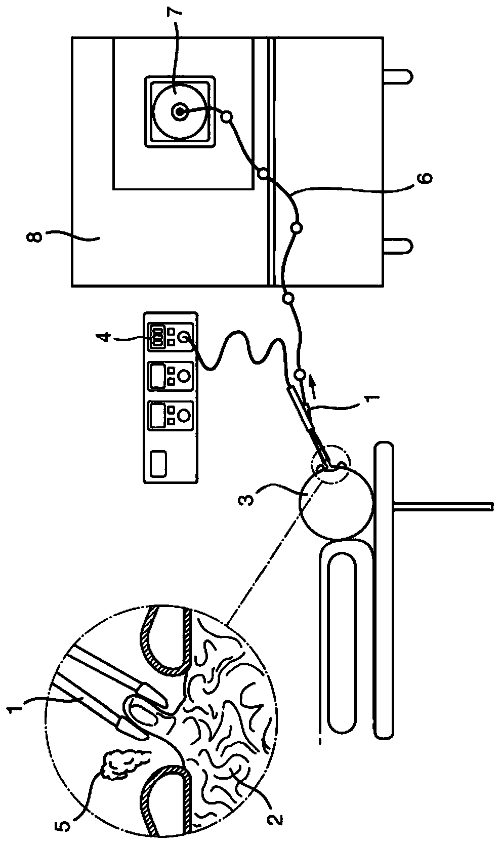
[0510]Various embodiments will now be described in more detail below, which generally relate to the use of ambient ionizing ion sources to generate aerosols, surgical smoke or vapor from one or more regions of a target (eg, tissue in the body).

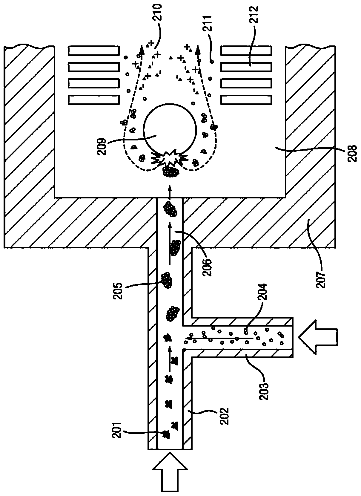
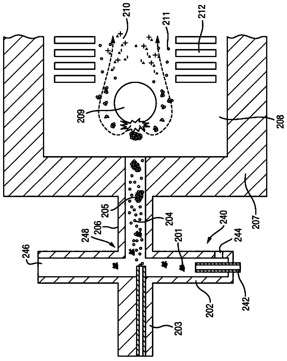
[0511] This aerosol, surgical smoke or vapor is then drawn into the vacuum chamber of a mass spectrometer and / or ion mobility spectrometer and impinged on an impact surface, causing the aerosol, smoke or vapor to be ionized by impact ionization , which results in the generation of analyte ions.

[0512] The resulting analyte ions (or fragments or product ions derived from the analyte ions) are then subjected to mass and / or ion mobility analysis, and the resulting mass and / or ion mobility spectral data can then be subjected to multivariate analysis, One or more properties of the object are determined in real time.

[0513] For example, the multivariate analysis may enable a determination to be made as to whether a portion of the curre...


PUM

PropertyMeasurementUnit
lengthaaaaaaaaaa
diameteraaaaaaaaaa
diameteraaaaaaaaaa

Abstract

An apparatus for performing ambient ionisation mass and / or ion mobility spectrometry is disclosed. The apparatus comprises a substantially cylindrical, tubular, rod-shaped,coil- shaped, helical or spiral-shaped collision assembly; and a first device arranged and adapted to direct analyte, smoke, fumes, liquid, gas, surgical smoke, aerosol or vapour onto said collision assembly.

Description

[0001] This application is a divisional application of the patent application with the application number 201680025657.0 and the title of the invention "collision surface for improving ionization" submitted on November 2, 2017. [0002] Cross References to Related Applications [0003] This application claims UK Patent Application No. 1503876.3 filed 6 March 2015, UK Patent Application No. 1503864.9 filed 6 March 2015, UK Patent Application No. 1518369.2 filed 16 October 2015, March 2015 UK Patent Application No. 1503877.1 filed on 6 March, UK Patent Application No. 1503867.2 filed on 6 March 2015, UK Patent Application No. 1503863.1 filed on 6 March 2015, UK Patent Application No. 1503863.1 filed on 6 March 2015 1503878.9, UK Patent Application No. 1503879.7 filed 06 March 2015 and UK Patent Application No. 1516003.9 filed 09 September 2015. The entire contents of these applications are incorporated herein by reference. technical field [0004] The present invention relates...

Claims


Application Information

Patent Timeline
Patent Type & Authority Applications(China)
IPC IPC(8): H01J49/00H01J49/04H01J49/06H01J49/16A61B10/00A61B10/02A61B17/32A61B18/04A61B18/18A61B18/20G01N33/68G01N33/92
CPCA61B10/02A61B17/00A61B17/32A61B18/00A61B18/14A61B18/20G01N3/00G01N9/00G01N27/622G01N33/68G01N33/92H01J49/00H01J49/04H01J49/06H01J49/16A61B10/0233A61B10/0283A61B17/320068A61B2218/008G01N33/6848H01J49/0404H01J49/0459H01J49/068A61B5/7264A61B5/00A61B5/14546A61B2505/05G01N27/626G16H20/00A61B2017/32007G16H10/40G16H50/20A61B10/00A61B10/0041A61B18/042A61B18/1815A61B2010/0083A61B2018/00577A61B2018/00589A61B2018/00994A61B2218/002H01J49/0027H01J49/0468H01J49/049G01N27/623G16B20/00H01J49/0036H01J49/0422H01J49/142A61B90/13A61B2017/320069G16H15/00A61B1/00013A61B1/041A61B1/31A61B5/0066A61B5/0075A61B5/015A61B5/055A61B5/14542A61B6/032A61B6/037A61B8/13A61B18/1445A61F13/38G01N33/487G01N33/48735H01J49/0004H01J49/0031H01J49/025H01J49/0409H01J49/0445H01J49/061H01J49/10H01J49/14H01J49/164H01J49/24H01J49/26A61B1/2736A61B5/0507A61B18/04C12Q1/025C12Q1/04C12Q1/18C12Q1/24G01N1/2202G01N27/624G01N30/724G01N33/6851G01N2001/2223G01N2333/195G01N2405/00G01N2405/04G01N2405/08G01N2570/00G01N2800/26H01J49/0463
Inventor 塔马斯·卡兰斯丹尼尔·西蒙拉约什·高迪尔海兹丹尼尔·绍洛伊史蒂文·德里克·普林格尔埃姆里斯·琼斯伊恩·崔维特斯蒂芬·奥布赖恩安东尼·赫斯马特·亨德森阿尔文·蔡佐尔坦·塔卡茨
Owner MICROMASS UK LTD
Why Eureka
Try Eureka