Distributed redundant constant-pressure water supply control system

A distributed control and control unit technology, applied in the field of online maintenance, energy-saving constant pressure water supply control system, and high reliability, which can solve the problems of inability to maintain normal pressure, frequent pressure maintenance, and incompetence for large-scale water supply systems.

Active Publication Date: 2020-02-07
许刚
View PDF7 Cites 5 Cited by
  • Summary
  • Abstract
  • Description
  • Claims
  • Application Information

AI Technical Summary

Problems solved by technology

If the central control unit breaks down, the entire system will be paralyzed, that is, "one damage and all damage"
In addition to this, another disadvantage of centralized control is that it cannot be maintained "online", that is, maintenance must be performed after the equipment is shut down, which affects the continuity of equipment water supply
[0027] 2. High after-sales cost
[0028] 3. The expansion ability is not strong, and it cannot be used for large-scale water supply systems
[0029] 4. During the peak period of water consumption, the pressure at the end of the pipe network is insufficient
[0030] Inaccurate judgment of the pressure-holding standby condition of the control system
At present, the general

Method used


Image

  • Distributed redundant constant-pressure water supply control system
  • Distributed redundant constant-pressure water supply control system
  • Distributed redundant constant-pressure water supply control system

Examples


Embodiment Construction

[0104] In order to illustrate the technical solution of the present invention more clearly, a typical embodiment in actual application is now selected and described in combination with the accompanying drawings. Apparently, the described embodiment is only one embodiment of the present invention, not all embodiments. Based on the embodiments of the present invention, all other embodiments obtained by those skilled in the art without creative efforts shall fall within the protection scope of the present invention.

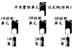
[0105] The pressurized pump group selected in the embodiment is a distributed redundant control system of 3 pumps, the appearance of which is as follows figure 1 shown.

[0106] 1. Hardware composition: The distributed redundant control system consists of 1 central management coordination unit, 3 independent distributed control units that can operate independently, 3 pumps, 6 digital sensors, and 6 analog sensors. One digital sensor and one analog sensor are inst...


PUM


Abstract

The invention discloses a distributed redundant control system. According to the system, pump revolution speed is dynamically adjusted based on the pressure, flow, temperature and other variables of fluid so as to achieve an expected control objective. The product is composed of one central management and coordination unit and n distributed control units which are independent and redundant from one another and can run autonomously, wherein each unit is in whole-network information transmission and modular design; the central management and coordination unit is only responsible for managing andcoordinating the control units, and the right of control is handed over to each control unit; and the central management and coordination unit can perform cascading in the same network segment or across network segments. In a pressure-maintaining standby state based on a multi-variable weight algorithm, the system does not do idle work due to dynamic flow compensation. The system has the advantages of high reliability, high continuity, distributed running, strong extensibility and energy preservation, therefore, the defects that through a traditional central control mode, reliability is poor,and equipment overhaul requires shutdown and water supply cut-off are overcome, and the problems that water supply continuity is not high, and the scale is not large in the industry are solved. In this way, the after-sales service pattern in the current industry is changed, and after-sales cost is greatly lowered.

Description

technical field [0001] The invention relates to a constant-pressure water supply control system, in particular to a high-reliability, on-line maintenance and energy-saving constant-pressure water supply control system. Background technique [0002] Basic Concepts in Constant Pressure Water Supply Control System [0003] Sensor (sensor): Pipeline pressure detection instrumentation, divided into digital / analog type, is the signal acquisition component of the control system. [0004] PLC (Programmable Logic Controller): The control core of the control system. Its functions are signal collection, calculation processing, and output of calculation processing results to the actuators. [0005] Driver (variable frequency drive): It is the terminal actuator of the control system, which uses electric energy to drive the pump unit to run. [0006] HMI (Human-Machine Interface): A touch screen for human-computer interaction, which visualizes the control process. [0007] The constant...

Claims


Application Information

Patent Timeline
IPC IPC(8): G05B19/418E03B1/00E03B7/07
CPCG05B19/4188E03B1/00E03B7/07Y02P80/10Y02P90/02
Inventor 许刚
Owner 许刚
Why Eureka
Try Eureka