
Connecting pipe structure

A technology for connecting pipes and nozzles, which is applied in the direction of pipes/pipe joints/fittings, pipes, branch pipelines, etc., which can solve the problems of copper pipe strength and fatigue resistance decline, inability to batch, high cost, etc., to shorten the preparation time, Energy saving and low price effect

Inactive Publication Date: 2020-02-11
佛山市智晓科技服务有限公司
View PDF0 Cites 0 Cited by
  • Summary
  • Abstract
  • Description
  • Claims
  • Application Information

AI Technical Summary

Problems solved by technology

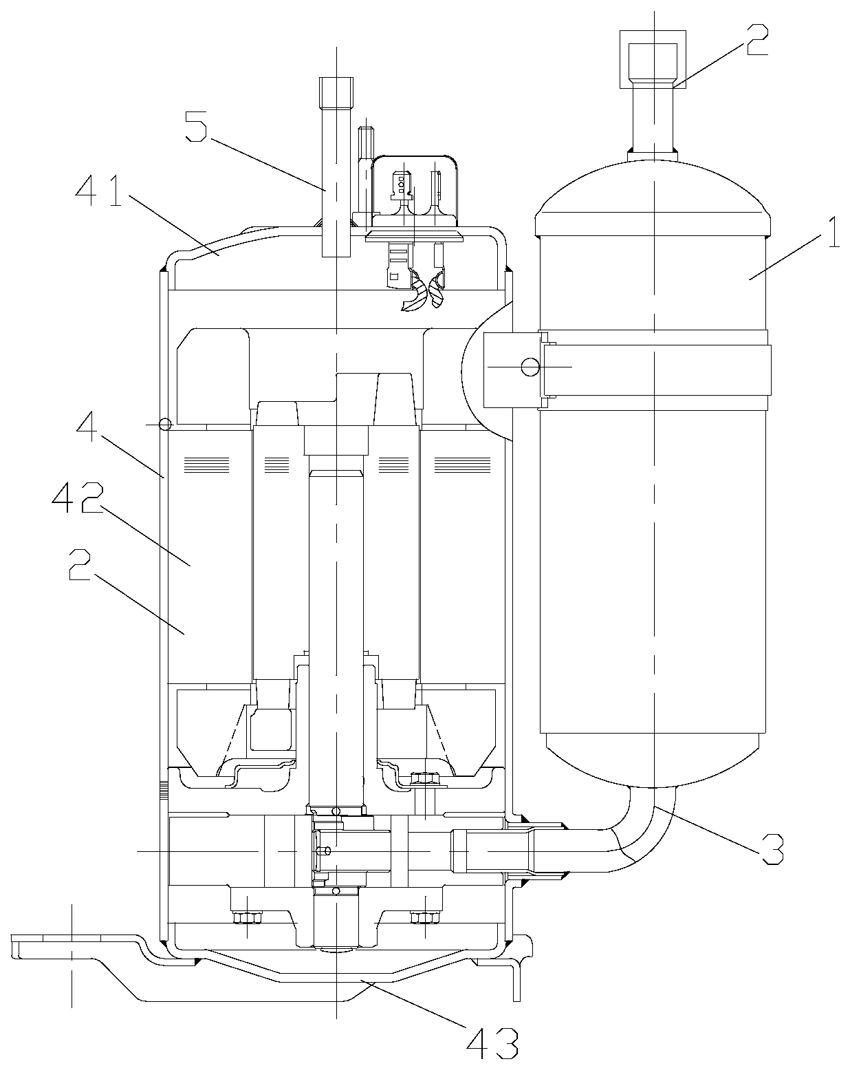
Among them, the outer nozzles of the upper connecting pipe 2 and connecting pipe 5 made of copper need to reserve at least 5 mm without paint adhesion for subsequent flame welding connection with the air-conditioning piping. Therefore, the upper connecting pipe 2 and the connecting pipe made of copper 5. The length of the exposed part of the shell is generally greater than 10mm. If the length is not enough, the subsequent welding process will damage the paint on the exterior of the iron shell and cause it to be corroded in the future.
However, since the grain size of the copper material will grow at high temperature, the strength and fatigue resistance of the copper tube will decrease. During long-term operation, the risk of fatigue fracture due to piping vibration is higher. Therefore, when preparing products with this structure, the welding of the iron connection base and the copper upper connection pipe 2 and connection pipe 5 cannot be carried out in batches. Welding, only flame welding can be used one by one
Therefore, adopting this kind of structure and manufacturing process has low efficiency, high cost and complex process

Method used


Image

  • Connecting pipe structure
  • Connecting pipe structure
  • Connecting pipe structure

Examples


preparation example Construction

[0027] The preparation method of the above-mentioned connecting pipe structure 7: the welding of the copper lining pipe 73, the iron connecting base 72 and the pipe body 71 can be performed during, before or after the aforementioned surface treatment process. When the temperature range of the surface treatment process is within the welding temperature (800-1082° C.) range of the copper lining pipe 73 , the welding can be completed synchronously during the surface treatment process. The copper lining pipe 73 is welded for subsequent welding with copper pipes or composite pipes with copper welding parts. Since phosphorus copper solder is generally used for subsequent welding with copper air-conditioning piping, and the welding temperature is above 720°C, it is preferable to use solder with a solder temperature of not lower than 800°C (such as tin bronze solder) for welding the copper lining pipe 73 and the pipe body 71 . Preferably, the welding condition of the copper-lined pipe...

Embodiment 1

[0038] Embodiment 1 (chromizing)

[0039] like Figure 4 As shown, in this embodiment, the connecting pipe structure 7 includes a pipe body 71. The pipe body 71 is a straight iron-based pipe, and a copper lining pipe 73 is welded in the mouth of one end of the pipe. The outer surface of the port starts from the edge of the port. The area (about 10 mm) extending to the other end with a distance D of not less than 5 mm has a corrosion-resistant layer 74; the other end is externally fixed with an iron connection base 72 for resistance welding connection with the shell.

[0040] One end of the pipe body 71 forms an anti-corrosion layer 74 (such as Figure 5 shown), then the copper lining pipe 73, the iron connection base 72 and the pipe body 71 are assembled as a whole and filled with solder, and sent to a high temperature furnace for welding. The welding condition is that the temperature is 800-1082 °C (this temperature is the furnace The actual temperature of the inner product...

Embodiment 2

[0044] Embodiment 2 (copper and iron diffusion)

[0045] like Image 6 As shown, in this embodiment, an anti-corrosion layer 74 is formed at one end of the pipe body 71 through a copper-iron diffusion process. The copper-iron diffusion process is to first plate copper to form a copper coating, and then heat at a high temperature to make the surfaces of copper and iron pipes diffuse mutually. Therefore, in this embodiment, the copper lining pipe 73 and the iron connection base 72 can be connected to each other after copper plating. Assemble with the tube body 71 and fill it with solder, then enter the high-temperature furnace to make the copper and iron interdiffused and weld the three at the same time, the condition is that the temperature is 800-1082°C (this temperature is the actual temperature of the product surface in the furnace) in a high-temperature furnace Overheat for 3 minutes or more. like Figure 7 As shown, the anti-corrosion layer 74 is a layer of copper-iron ...


PUM

PropertyMeasurementUnit
thicknessaaaaaaaaaa
pore sizeaaaaaaaaaa
pore sizeaaaaaaaaaa

Abstract

The invention discloses a connecting pipe structure. An iron base material pipe serves as a pipe body, a copper lining pipe is connected in a pipe opening in one end of the pipe body in a welded mode,and a corrosion resistant layer formed through the surface treatment technology of the chromium plating technology or the nickel plating technology or the copper-iron dispersing technology or the chromium permeating technology, carbon-chromium permeating technology or the molybdenum permeating technology or the carbon-molybdenum permeating technology or the nitride permeating technology or the carbon-nitride permeating technology is arranged on the area which is not smaller than 3 mm from the edge of a port on the outer surface of the port with the copper lining pipe, and an iron connecting base used for carrying out welding with a shell is welded outside the other end of the pipe body. According to the connecting pipe structure, iron is adopted as a base material, the price is low, and welding connection with other copper material pipes in a later stage is convenient; meanwhile, the corrosion resistant layer is formed on the outer wall of the port through the surface treatment technology, and thus the port is fearless of flames at high temperatures, so that a welding position 5 mm or wider does not need to be reserved, the risk of breakage of the copper pipe is basically eliminated, the copper lining pipe, the pipe body and the connecting base can be assembled and subjected to furnace welding at a time even the connecting base is welded to the pipe body, the preparing time isgreatly shortened, and energy consumption is greatly reduced.

Description

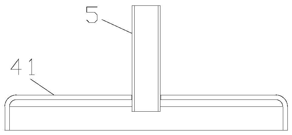
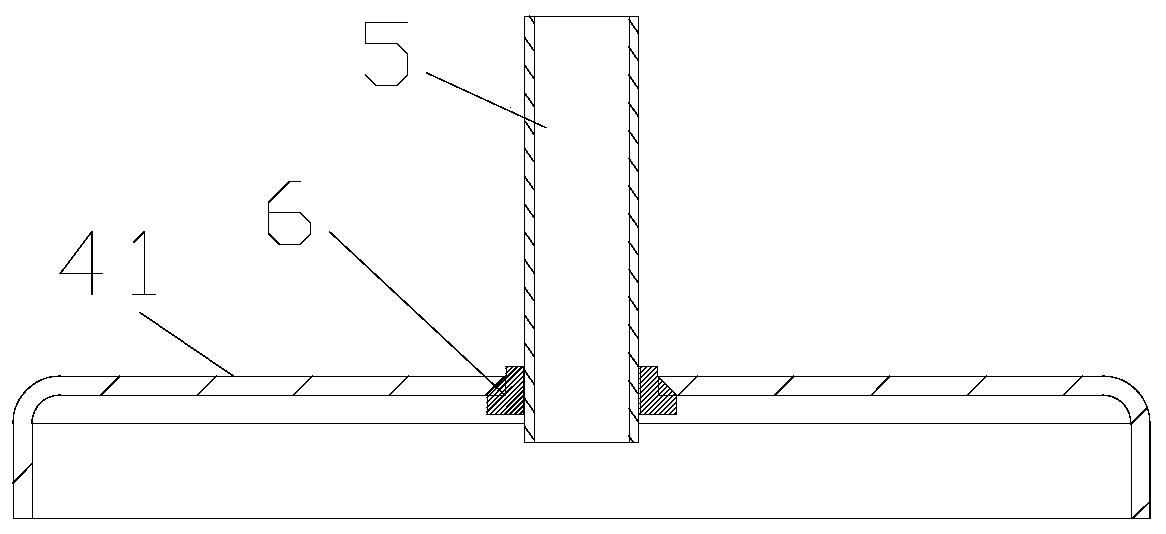
technical field [0001] The invention relates to the field of air conditioners, in particular to a connecting pipe structure. Background technique [0002] like figure 1 , 2 As shown, the existing air conditioner compressor liquid accumulator includes a housing 1 , an upper connecting pipe 2 and a lower connecting pipe 3 . The compressor generally includes a casing 4 (generally composed of three parts: an upper end cover 41, a cylinder body 42 and a lower end cover 43 (three-part structure) or two parts (a two-part structure) consisting of an upper cylinder body and a lower cylinder body (two-part structure)), Connect pipe 5 etc. The connection pipe 5 and the housing 4 are welded by resistance welding, and an iron connection base 6 needs to be added between the two, such as image 3 shown. [0003] Since the piping of the air conditioner is a copper pipe, the traditional upper connecting pipe 2 and the connecting pipe 5 are all made of copper, but the price of copper is ...

Claims


Application Information

Patent Timeline
Patent Type & Authority Applications(China)
IPC IPC(8): F16L41/08F16L58/04C23C8/32C23C12/02C23C30/00C25D3/12
CPCC23C8/32C23C12/02C23C30/00C25D3/12F16L41/084F16L58/04
Inventor 不公告发明人
Owner 佛山市智晓科技服务有限公司
Learn More