Biomass fuel particle and processing device and method thereof

A biomass fuel and fuel processing technology, applied in the direction of biofuel, waste fuel, raw material extrusion granulation, etc., can solve the problem of inability to control the size of biomass fuel particles, achieve good pressing effect, high molding rate, smooth running effect

Active Publication Date: 2020-02-14
吉林省尚心能源有限责任公司
View PDF5 Cites 13 Cited by
  • Summary
  • Abstract
  • Description
  • Claims
  • Application Information

AI Technical Summary

Problems solved by technology

However, the device cannot control the size of the biomass fuel pellets

Method used


Image

  • Biomass fuel particle and processing device and method thereof
  • Biomass fuel particle and processing device and method thereof
  • Biomass fuel particle and processing device and method thereof

Examples


specific Embodiment approach 1

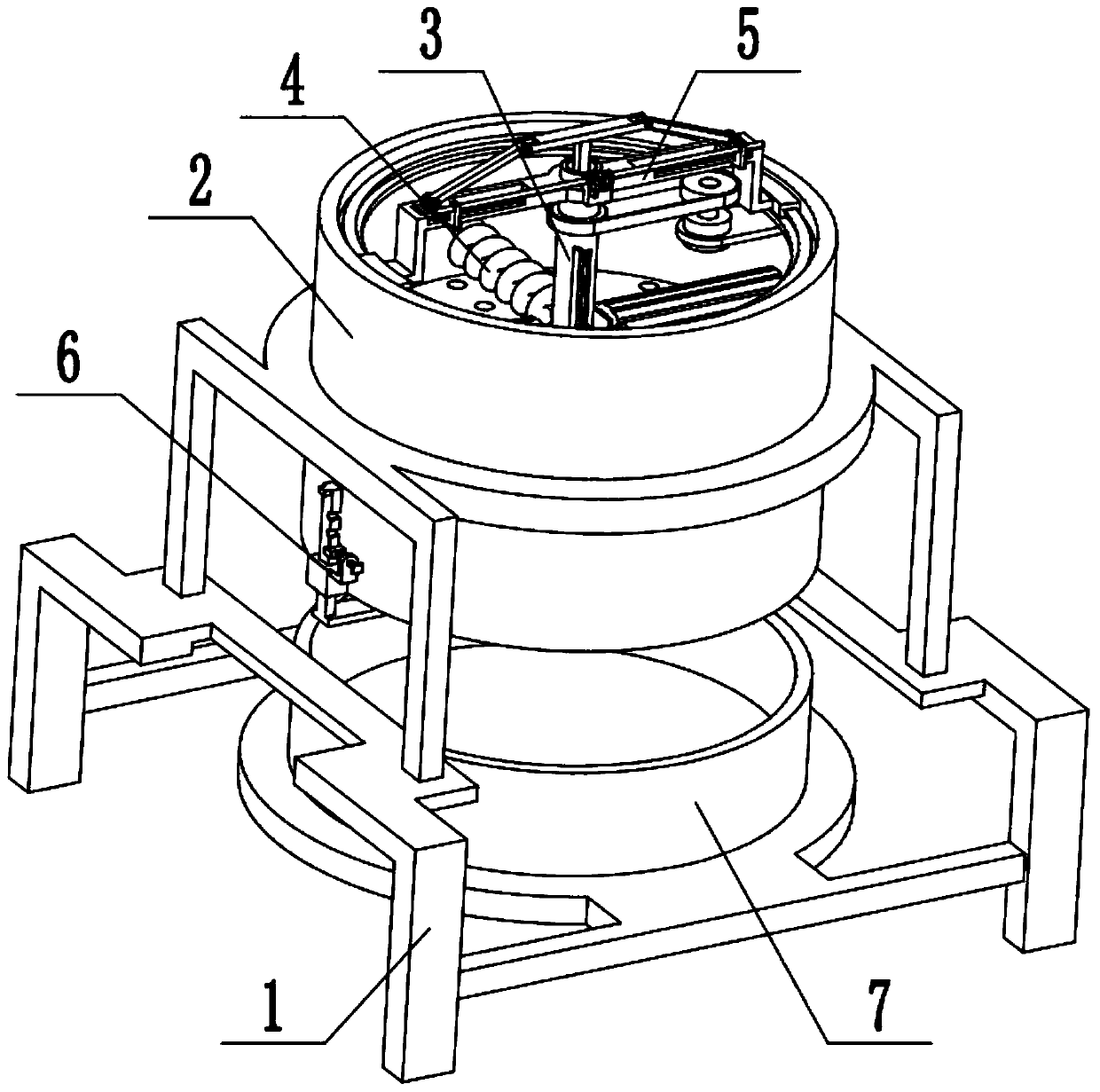
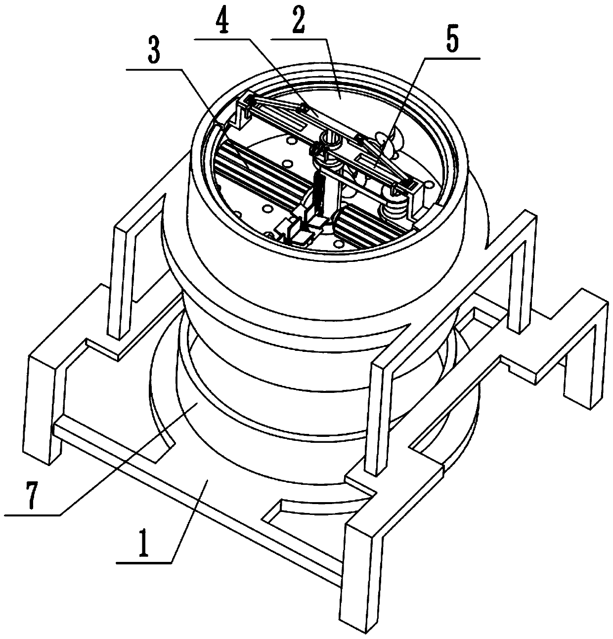
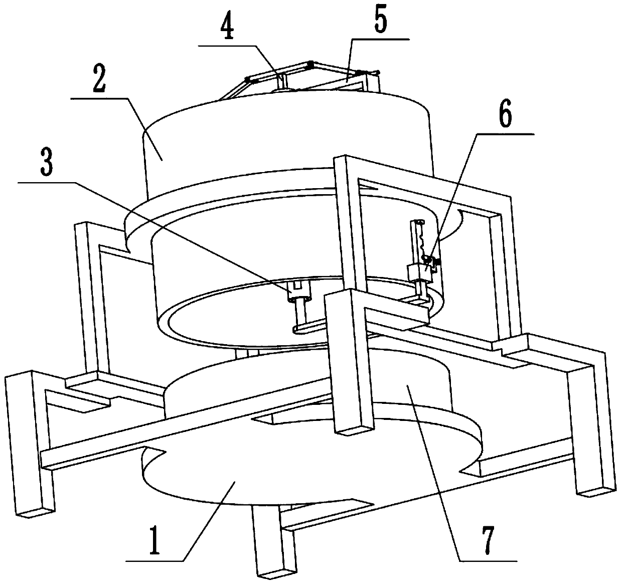
[0035] Combine below Figure 1-9 Describe this embodiment, a processing device for biomass fuel particles, including a support frame 1, a fuel processing cylinder 2, a particle processing driver 3, a fuel stirring and crushing mechanism 4, a reciprocating drive assembly 5, a cutting knife mechanism 6 and a receiving box 7. The fuel processing cylinder 2 is set on the support frame 1, the material receiving box 7 is placed on the support frame 1, the material receiving box 7 is located at the lower end of the fuel processing cylinder 2, and the particle processing drive member 3 is arranged on the fuel processing cylinder 2 Above, the particle processing drive part 3 is in transmission connection with the fuel processing cylinder 2, the lower end of the fuel stirring and crushing mechanism 4 is connected with the particle processing drive part 3, the upper end of the fuel stirring and crushing mechanism 4 is movably connected with the reciprocating drive assembly 5, and the reci...

specific Embodiment approach 2

[0037] Combine below Figure 1-10 To illustrate this embodiment, the support frame 1 includes a base plate 1-1, a side frame 1-2, a door frame 1-3 and a ring seat 1-4; the receiving box 7 is placed on the base plate 1- 1, the two ends of the base plate 1-1 are respectively fixedly connected to a side frame 1-2, and the two side frames 1-2 are respectively fixedly connected to a door frame 1-3, and the ring seat 1-4 is fixed Connected between the two gate frames 1-3, the fuel processing cylinder 2 is fixedly connected to the ring seat 1-4.

specific Embodiment approach 3

[0039] Combine below Figure 1-10 To illustrate this embodiment, the fuel processing cylinder 2 is provided with a trapezoidal ring seat 2-1, a ring frame 2-2, a circular hole seat plate 2-3, and a driving bevel gear 2-4; The upper end is fixedly connected to the ring frame 2-2, and the ring frame 2-2 is provided with a trapezoidal ring seat 2-1, and the circular hole seat plate 2-3 is fixedly connected to the middle end of the fuel processing cylinder 2, and the driving bevel gear 2-4 Fixedly connected on the round hole seat plate 2-3, the particle processing driving part 3 is arranged on the round hole seat plate 2-3, a plurality of circular through holes are uniformly distributed on the round hole seat plate 2-3, the particle processing driving part 3 is connected with the drive bevel gear 2-4, and the reciprocating drive assembly 5 is movably connected with the trapezoidal ring seat 2-1, and the reciprocating drive assembly 5 can rotate on the trapezoidal ring seat 2-1. P...


PUM


Abstract

The invention relates to a biomass fuel particle and a processing device and method thereof. The biomass fuel particle is prepared from the components: 15 parts of rice husks, 25 parts of straw, 10 parts of wood scraps, 3 parts of corn cobs, 35 parts of rice and wheatgrass, 5 parts of tree roots, 35 parts of wood chips, 10 parts of bagasse, 5 parts of cottonseed shells, 3 parts of a dehydrator, 1part of pecan shells and 1 part of bamboo chips. The processing method includes the following steps that step 1, biomass fuel is put into a fuel processing cylinder; step 2, a reciprocating drive assembly starts to drive a stirring plate and a spiral stirring blade move up and down in a reciprocating mode, and the biomass fuel is rotated and stirred up and down in a reciprocating mode; step 3, a particle processing driving part starts to drive two pressing rollers to rotate, and the two pressing rollers extrude the biomass fuel from a circular through hole by the cooperation with a round holeseat plate; step 4, the particle processing driving part drives a cutting knife mechanism to rotate, and the rotary cutting knife mechanism cuts the extruded column-shaped biomass fuel into grain shape; and step 5, biomass fuel particles fall into a material receiving box to be collected.

Description

technical field [0001] The invention relates to the technical field of biomass particle fuel, and more specifically relates to a biomass fuel particle, a processing device and a processing method thereof. Background technique [0002] The existing patent number is CN201720897342.7 for a biomass fuel pellet machine. The utility model patent relates to the technical field of biomass fuel pellets, and specifically relates to a biomass fuel pellet machine. The fuel pellet machine includes a lower hopper, an extrusion silo, and a feed silo that are sequentially arranged above the frame. The center of the extrusion silo is provided with two intermeshing gears, and the bottom is provided with a mold plate. The transmission mechanism is connected by transmission; the upper part of the feeding bin is provided with a material inlet, and the inside is provided with a screw auger; the outer part of the lower bin is provided with a material inlet, and the center of the lower bin is provi...

Claims


Application Information

Patent Timeline
Patent Type & Authority Applications(China)
IPC IPC(8): C10L5/44B01J2/20B01F11/00
CPCC10L5/445C10L5/442B01J2/20B01F31/40Y02E50/10Y02E50/30
Inventor 朱力
Owner 吉林省尚心能源有限责任公司
Why Eureka
Try Eureka