Method for recovering carbon dioxide by multistage liquefaction and staged refrigeration of industrial tail gas

A technology for industrial tail gas and carbon dioxide, applied in separation methods, chemical instruments and methods, chemical industry, etc., can solve the problems of low carbon dioxide yield and high energy consumption of devices, so as to improve refrigeration efficiency, reduce system energy consumption, and improve thermal cycle Effect of Efficiency and Cooling Coefficient

Active Publication Date: 2020-02-18
杭州快凯高效节能新技术有限公司
View PDF29 Cites 2 Cited by
  • Summary
  • Abstract
  • Description
  • Claims
  • Application Information

AI Technical Summary

Problems solved by technology

[0003] In response to the above problems, the Chinese patent disclosed a utility model patent on 2018.03.10 called a low-temperature methanol washing flash tower second-stage flash vapor recovery system (application number: CN201820326875.4), in which the liquid CO 2 The recovery system includes fine desulfurization tower, purification tower, CO 2 Gas compressor, precooler, ammonia condenser, separation column and product CO 2 Storage tank; the flash gas enters the fine desulfurization tower after passing through the water cooling device, and the flash gas after desulfurization goes to the purification tower. In the purification tower, high boiling substances such as methanol and water in the flash gas are absorbed, and the ...

Method used


Image

  • Method for recovering carbon dioxide by multistage liquefaction and staged refrigeration of industrial tail gas
  • Method for recovering carbon dioxide by multistage liquefaction and staged refrigeration of industrial tail gas
  • Method for recovering carbon dioxide by multistage liquefaction and staged refrigeration of industrial tail gas

Examples


Embodiment Construction

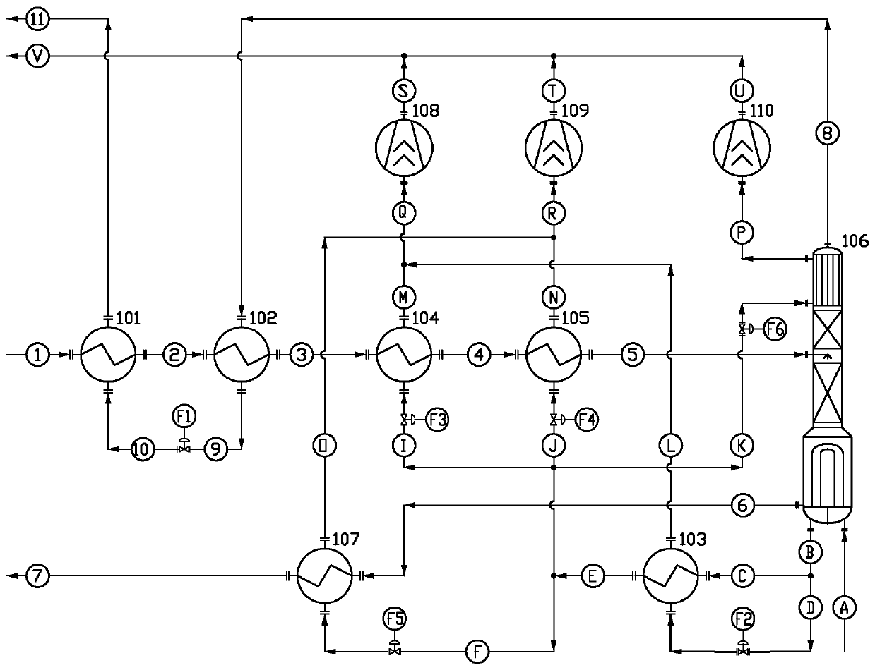
[0044] like figure 1 As shown, it is a method for recovering carbon dioxide by multi-stage liquefaction of industrial tail gas and graded refrigeration of the present invention, including a first residual cold recovery device 101, a second residual cold recovery device 102, a primary condenser 104, a secondary condenser 105, a finishing Distillation tower 106, subcooler 107; feed gas pipeline 1, feed gas pipeline 2, feed gas pipeline 3; feed gas gas-liquid mixing pipeline 4, feed gas gas-liquid mixing pipeline 5; product pipeline 6, product pipeline 7.

[0045] The specific steps are as follows: after drying and dehydration, the 3.3MPa, 38°C raw material gas passes through the raw gas pipeline 1 and first enters the first residual cold recovery device 101, and is pre-cooled to 22°C by exchanging heat with the non-condensable gas, and then passes through the raw gas pipeline 2 Go to the second waste cold recoverer 102, and exchange heat with non-condensable gas to be pre-cooled...


PUM


Abstract

The invention discloses a method for recovering carbon dioxide by multistage liquefaction and staged refrigeration of industrial tail gas, wherein the method comprises the following steps: raw material gas firstly enters a first residual cold recoverer, exchanges heat with non-condensable gas, is pre-cooled to 22 DEG C, then enters a second residual cold recoverer, exchanges heat with the non-condensable gas, and is pre-cooled to 16 DEG C; then the pre-cooled raw material gas enters a primary condenser, is cooled to -18 DEG C through ammonia evaporation refrigeration, then enters a secondary condenser, and is cooled to -25 DEG C through ammonia evaporation refrigeration; then the treated gas enters a rectifying tower to be rectified and purified, a tail condenser arranged at the top of therectifying tower cools the tail condensed gas to -45 DEG C through ammonia vacuum evaporation, and a qualified industrial-grade or food-grade liquid CO2 product is extracted from the tower kettle ofthe rectifying tower; the product is sent to a supercooler through a product pipeline, is supercooled to -25 DEG C through ammonia evaporation refrigeration and then is sent to a product storage tankthrough a product pipeline. The technological process is clear in hierarchy, low in working pressure and low in equipment manufacturing difficulty, the refrigeration coefficient of a refrigeration system is increased, meanwhile, the yield of the CO2 system is increased, and the purposes of saving energy and reducing consumption are achieved.

Description

technical field [0001] The invention belongs to the technical field of recovering carbon dioxide, and in particular relates to a method for recovering carbon dioxide through multi-stage liquefaction and graded refrigeration of industrial tail gas. Background technique [0002] At present, coal and oil are still the main energy consumption of human beings. In the primary energy consumption structure, coal accounts for 68.5%, oil accounts for 17.7%, and natural gas accounts for only 4.7%, which is far lower than the world average of 24%. In the late regeneration stage of the decarbonization liquid of the low-temperature methanol eluting carbon device and the early stage of the regeneration of the adsorbent of the PSA decarburization device, a tail gas with a medium and low carbon dioxide concentration (75% to 85%) will be produced. [0003] In response to the above problems, the Chinese patent disclosed a utility model patent on 2018.03.10 called a low-temperature methanol was...

Claims


Application Information

Patent Timeline
IPC IPC(8): B01D5/00B01D3/14C01B32/50
CPCB01D3/14B01D5/0036C01B32/50Y02P20/10Y02P20/129Y02P20/50Y02P70/10
Inventor 徐美南唐志飞钟长孝
Owner 杭州快凯高效节能新技术有限公司
Why Eureka
Try Eureka