
Conical spiral bubble conveying device and preparing method thereof

A technology of bubbles and spirals, which is applied in the field of bubble transportation devices and its preparation, can solve problems such as pipeline corrosion and shorten equipment life, and achieve the effect of eliminating corrosion

Pending Publication Date: 2020-02-21
ZHEJIANG UNIV OF TECH
View PDF0 Cites 0 Cited by
  • Summary
  • Abstract
  • Description
  • Claims
  • Application Information

AI Technical Summary

Problems solved by technology

Furthermore, when the presence of air bubbles leads to adverse effects, such as CO in aqueous media 2 or H 2 S microbubbles will accelerate the hydrogenation of metals and form hydrogen pores on the surface, which in turn will cause severe corrosion of pipelines and shorten the life of equipment. Most of the traditional methods chosen to eliminate bubbles utilize buoyancy, including chemical methods and physical methods, but they are not effective for complex spaces. The elimination of air bubbles in the structure often also requires the operation of anti-buoyancy

Method used


Image

  • Conical spiral bubble conveying device and preparing method thereof
  • Conical spiral bubble conveying device and preparing method thereof
  • Conical spiral bubble conveying device and preparing method thereof

Examples


Embodiment 1

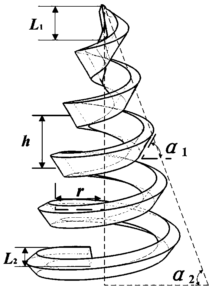
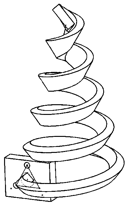
[0035] Referring to the accompanying drawings, the cone-helix air bubble transport device includes a cone-helicoid, and the structure of the cone-helicoid in the three-dimensional space coordinate system is as follows:

[0036] The inclination angle to the Z axis is α 1 , the side length is L 2 A regular quadrilateral, from the bottom along the pitch h, the taper is The spiral line of the regular quadrilateral gradually increases upwards, and the two vertically opposite sides of the regular quadrilateral increase linearly to L 1 , the base radius of the helix is ​​r, and the number of rotations is n.

[0037] Use 3D software to model, and make the bionic cone helix take the following structural parameters: α 1 =45°, α 2 =30°, L 1 =3 mm, L 2 =1mm, h =5 mm, n =7, r =10 mm; 3D printing technology can be used to prepare three-dimensional cone and helix.

[0038] The cone-screw device of the present invention is fixed on the base, and then the base is installed at th...

Embodiment 2

[0040] With reference to the accompanying drawings, this example adopts the following steps on the basis of the cone screw device prepared in embodiment one:

[0041] Step 2, preparing rough micro-nano structure: using femtosecond laser to scan the surface of the pyramidal helicoid to obtain rough micro-structure;

[0042] Step 3, prepare super-hydrophobic substrate: use a brush to dip an appropriate amount of super-hydrophobic solution to evenly coat the inner surface of the cone spirochetes, and dry the sample on the surface of the drying table adjusted to 60 °C for 15 minutes to ensure that the solvent is completely Volatilize, then repeat dipping, coating, and drying five times;

[0043] Step 4: Add HFE7100 lubricant dropwise, blow the surface with a hair dryer to remove excess lubricant, and form a lubricating film on the surface of the substrate.

[0044] The cone spirochete described in this example can be used in a liquid environment due to the superhydrophobic treatm...


PUM


Abstract

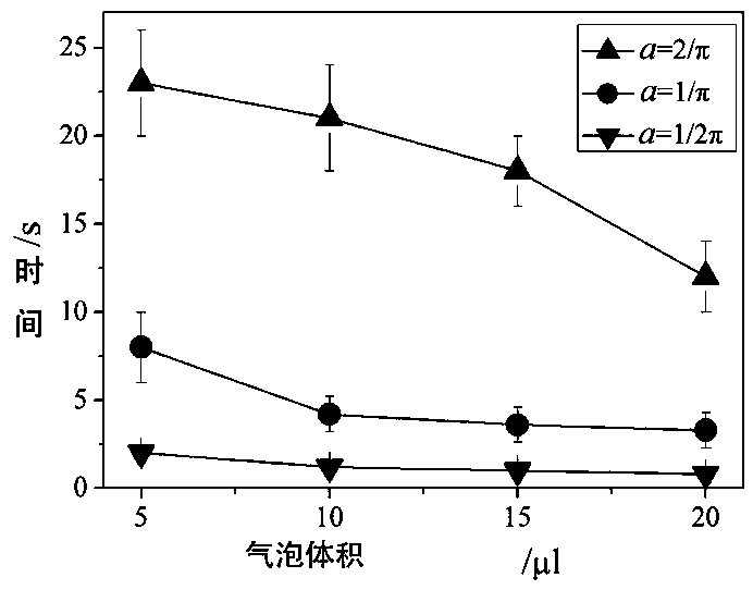
The invention discloses a conical spiral bubble conveying device which comprises a conical spiral body. The conical spiral body begins to be upwards gradually contracted to the contracting end from the starting end. The starting end of the conical spiral body is an inclined quadrangle, and the vertical edges of the quadrangle are gradually increased upwards along the conical spiral. A wedge anglecan generate Laplace force on bubbles only if the diameter of the bubbles is larger than the height of the inner side face of the conical spiral body, meanwhile, the curvature of the conical spiral isused for generating the curvature driving force on the bubbles, and under the common effect of the Laplace force and the curvature driving force, the bubbles can be driven to move towards a conical top by means of the conical spiral bubble conveying device. Anti-gravity and anti-buoyancy transportation on the bubbles is achieved.

Description

technical field [0001] The invention relates to a bubble transport device and a preparation method thereof, in particular to a cone-screw bubble transport device and a preparation method thereof. Background technique [0002] Bubble generation, controllable collection, and directional transport play important roles in many modern scientific and technological fields. For example, air bubbles have important applications in many natural and technological processes, such as in polymerization, dispersion, extraction, production of detergents and cosmetics, and liquid boiling and condensation processes; in liquid environments, bubbles in four-dimensional color Doppler ultrasound, material transmission , Particle flotation, water purification, electrochemistry, anti-corrosion, drag reduction and other fields have important applications. [0003] How to make bubbles realize anti-gravity self-transport in the air environment, overcome the effect of gravity, and change the transport ...

Claims


Application Information

Patent Timeline
Patent Type & Authority Applications(China)
IPC IPC(8): B65G33/00B65G33/26B23K26/352B29C64/10B05C1/02B05C9/14
CPCB65G33/00B65G33/265B23K26/352B29C64/10B05C1/02B05C9/14
Inventor 吴化平卓江山徐璞杨哲
Owner ZHEJIANG UNIV OF TECH
Learn More